Random Things - imbueFX

Hey Bill!
Welcome to the forums. Not only are you a talented artist, but you are also a wonderful teacher. I’ve always enjoyed listening to your lectures because they are so well thought out and inclusive. Looking forward to spending more time collaborating together. :slight_smile:

3 Likes

Yes the fake lighting model is done entirely in the material. I made a little gif that will hopefully help you understand the setup with some simple outlines.

The blue spherical volume represents the light’s radius in world space. The arrow in the middle in the vector from the center of the light to the camera.

Since the simple lighting model is rendering behind the translucent octagon sprite, we need to make sure its always on the outside of the spherical radius. As the radius changes in size, the octagon pushes away as well as scales larger to accommodate. At a certain point this becomes less and less of a savings the larger it gets, but this is great for small details like screens, beacons, etc etc.

6 Likes

Love your work Bill! Used to watch the imbueFX videos as well when I was starting out in FX.

I wanted to ask about that transition effect on the ground that you made for the Fortnite custom mode. I saw you talking about it a bit in the Math for Artist video, but I don’t understand exactly how the entire thing functions? I assume a Blueprint drives the values, but what kind of values exactly?

Thanks for the cool information you keep sharing!

2 Likes

This is really awesome! Is there any more information you can offer for someone that doesn’t understand derivatives and doesn’t have a Daniel Wright at hand? :sweat_smile:

Is it using DDX / DDY? If so, what does it calculate the derivatives from with those nodes? And how do they combine to yield the exponent used for the fresnel?

Thanks Bill, I get it! This is very clever!
So from what I understand, the WorldPositionBehindTransluency can really help you fake a lot of things on a material, your approach seem close to this example:

I also stumbled upon this tweet by Chris Murphy which shows a different approach to using the function (here to fake a post process):

3 Likes

@AntonDessov Thank you! The color changing tile? Yes that’s just a blueprint with an overlap volume. When a player pawn overlaps and meets all the conditions (it has different gameplay options on it that I won’t get too into), it does a set of transforms to put the overlap point from world space to local UV space. The mesh itself is just a cuboid with a planar projection from top-down. Then it drives a spherical gradient with some other material work for flare to change from one color to another.

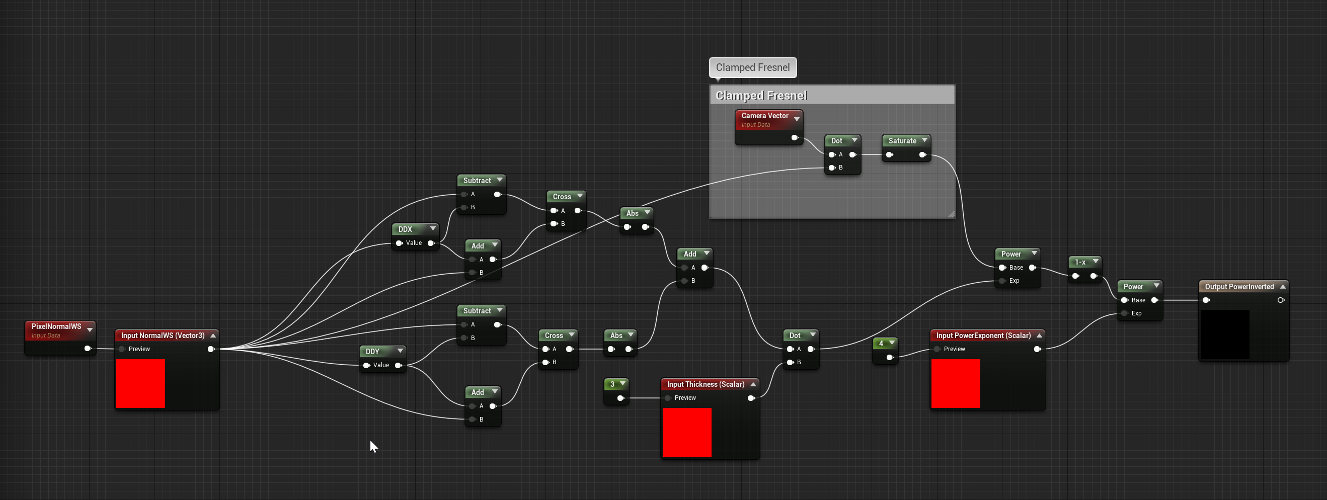
@CuddlyBunny Correct, it’s using calculating the derivatives of pixel normal or a normal map that’s transformed to world space. We just add and subtract the derivatives and then cross them. I use a dot to change it to a scalar, and that’s what drives the exponent on a basic fresnel. To be fair, it’s based more or less on this material code, give credit where credit’s due:

http://madebyevan.com/shaders/curvature/

Here’s a screen grab of my function if you’d like to use it

@MrBrouchet Yup! The spheremask Chris is showing is part of the same setup I’m using. The other major part is sample the world normal gbuffer so we can mask out the spheremask on surface normals that are facing away from the center.

6 Likes

Nice! I had not thought of doing that for something like a door! I assume you’re still triggering the material animation with a BP, and maybe a timeline?

Also, thanks for sharing this stuff, and for posting here! I hope your life calms down now! Your GDC talk was really great, BTW. Super eye opening to ways of being self sufficient on a large scale.

Dude, that looks really nice. Feels very physical.

1 Like

This is a literal goldmine for me, thanks a lot for all the great tips Bill, you are the hero I needed :smiley: And you are so right about vector math, back in school days I doubted that I’d ever need math for my art needs but lo and behold :smiley: Thanks again for all the resources :100::heart:

1 Like

@BrianKohrman Hey nice to hear from you again! In this instance, yes a blueprint is driving parameters on the door MID via a timeline. You can get smarter and do something I call “time stamping”, in which you just set a single scalar parameter that is just the game clock. In the material, you can do (game time - timestamp) and saturate that value to keep in a 0-1 range. Now you’ve just created a simple linear curve that can drive whatever you want! I’ll have to do a much deeper dive on this at some point.

2 Likes

That’s awesome, thanks a lot! This is exactly the level of shader math that I can wrap my head around, understand what’s happening and get better at it. Sometimes it’s really hard to connect your “current knowledge” of shader math to some more difficult problems when they are way above your level. At least that’s what its like for me sometimes. Then it’s very hard to learn and get better to come up with stuff like this on your own.

1 Like

Oh, dang, that is a good idea- much more efficient. I think I’m going to do some similar things with Niagara code now, too.

Hey Bill! Really nice seeing you post here. You and the tutorials on imbuefx were probably a big reason how I got to where I am today. I remember writing to you back in 2013 thanking you :smiley: Really cool to see what you’re up to now!

1 Like

One element I rely on heavily in materials are all things procedural. It’s important to define what that means (at least in my opinion), which is defining things mathematically rather than just looking up a texture.

While this does start with an actual texture of an eye, this little guy has all sorts of movement and character to it because of elements defined in the material. One element is the 8-bit feel of the screen.

Here’s a trick I use very, very frequently: In the context of UV coordinates, you think of these typically being a 0-1 range lookup into a texture.

If you think of these values as linear curves, we can adjust those curves to appear more stair-stepped, that we render “blocks” of the same texture coordinate over and over.

Another way of visualizing the difference between linear to stepped is just with a line graph. This is often called a “stepped curve”, as it actually resembles steps.

The most basic form of achieving this in a material is with this setup here.

With this knowledge, we can apply it past coordinates and also use this over time to give a staccato feeling to movement. This is really powerful with things like lightning, tech screens, you name it. Here’s an example of a fractional time value going from 0 to 1 with 8 steps.

Where we are taking a normalized set of values, multiply by the amount of steps we want, and using something like ceil/floor/round/truncate to give us whole integers, then dividing them back down by our amount of steps to bring everything back to 0-1.

We can combine these multiple approaches together like in the example below.

Where literally everything is generated procedural, even down to the little LCD circles. The sweep is a simple linear gradient that’s stepped, but also pans up using stepped time.

22 Likes

How do you deal with the moire patterns? Do you soften results with distance, or fade between multiple versions or something?

1 Like

Glad to see you here Bill! I’ve been a fan since the imbue days and have been following your career since. Looking forward to what all you have in that folder. I should do the same and share more of what I’m doing. We’ll hopefully this will inspire me to get more out there.

1 Like

@Niels It depends. Softer things like gradients tend not to show the issue too much for me. More complex patterns do, so I’ve done things like changing values or fading based on distance just as you suggested. If it’s critical, I’ll use this suggestion made from Wyeth in this post

@DavidSchoneveld Good to hear from you again David! I’d be curious to see what you’ve been doing lately.

@andre Thank you!

2 Likes

Here’s a really fun and unique one to share. In Creative Mode, we released a set of reactive props that changed based on music. So you can place the radio prop in your island, pick a track, and the audio file has FFT data baked into it. Through a blueprint interface (and some custom code), we’d write 5 different frequencies to a material parameter collection. Each block would pick from one of the frequencies and change all sorts of material properties to make it come alive.

Here’s an early WIP isolating how the materials work using some debug noise.

9 Likes

This was some exploration work for the Outlander class in Save The World, I believe for some sort of phase shift. I don’t believe this was used in the end, but I always enjoyed the material work on the character.

6 Likes

Here’s another of the Outlander’s skills. This one was unique because it utilized a spline system I wrote in blueprints and can curve meshes behind it for amazing fidelity.

The blueprint tracks a single vector in world space on tick (every frame). It updates the last point in the spline to that world position. Once the distance between the two points reaches a certain threshold, it will add a new point and start moving that. It also respects things like lifetime, size, rotation, etc etc.

All it takes it just attach the spline actor to a point that you want to emit trails from, like a character’s socket. Even with simple shapes, you can get excellent volume and shape in your FX.

If you want to have fun and play with the blueprint yourself, download it here!

http://gofile.me/2n5ae/28rUvI0aO

20 Likes