Hey Folks I’m switching over to UE4 from Unity and I’m trying to accelerate my learning to catch up to where I need to be. I’ll be posting questions about Cascade & Materials in UE4.
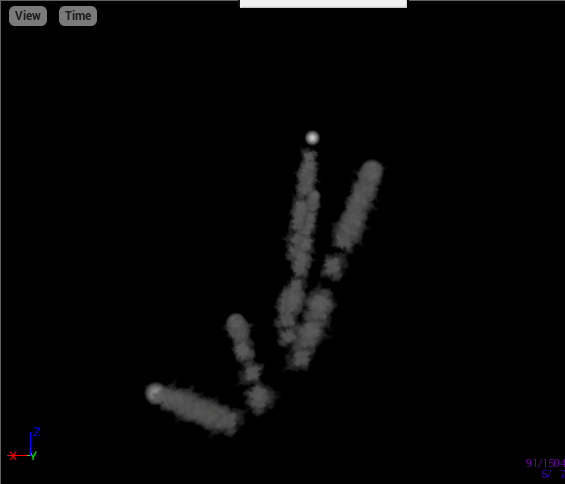
I’ve been tasked with reverse-engineering rain FX from the previous Environment FX Artist. I’ve been given permission to post for help. The main issue here is the rain’s visibility. I want help finding a proper solution to increasing its visibility without sacrificing its visual quality.
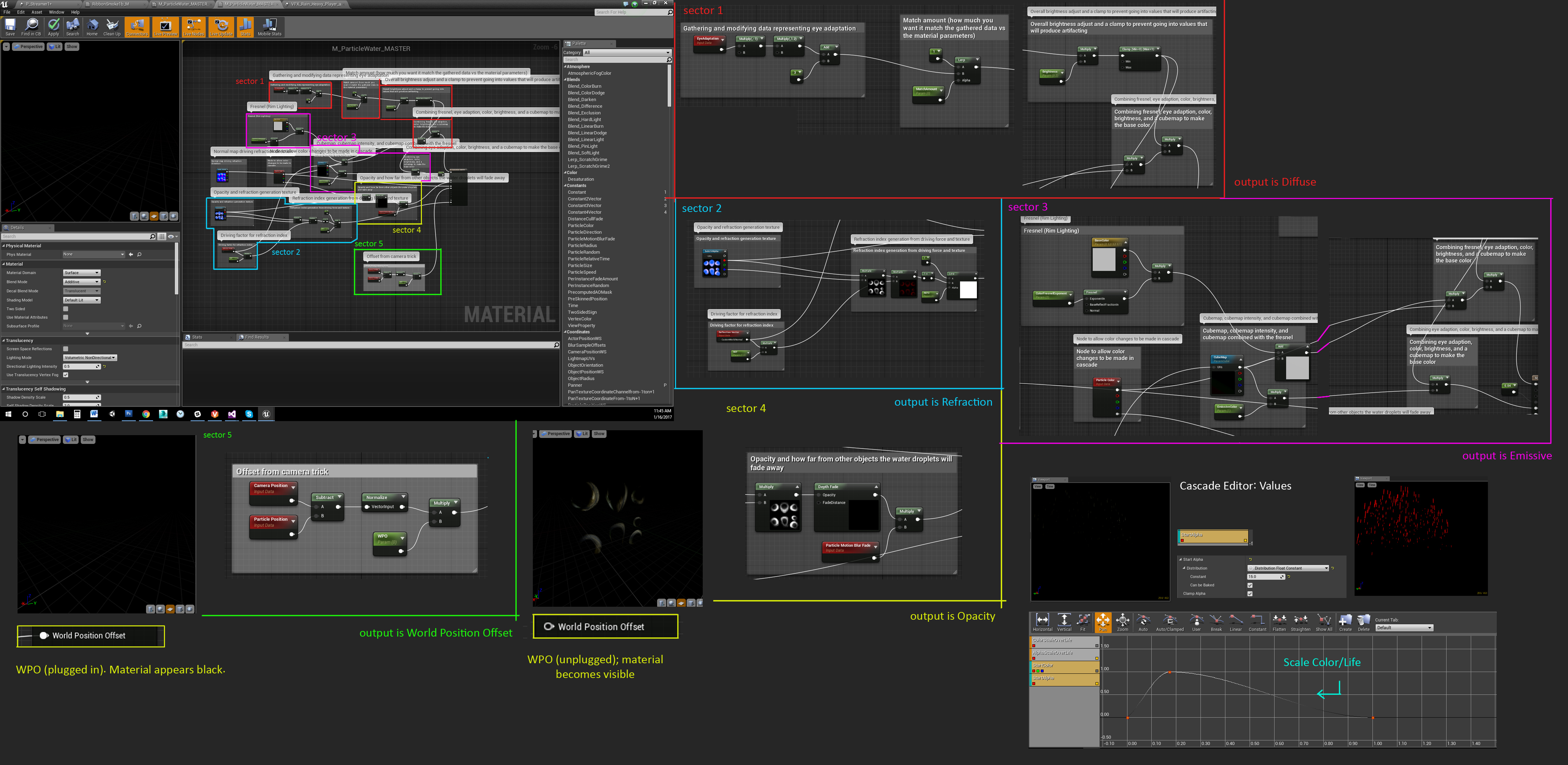
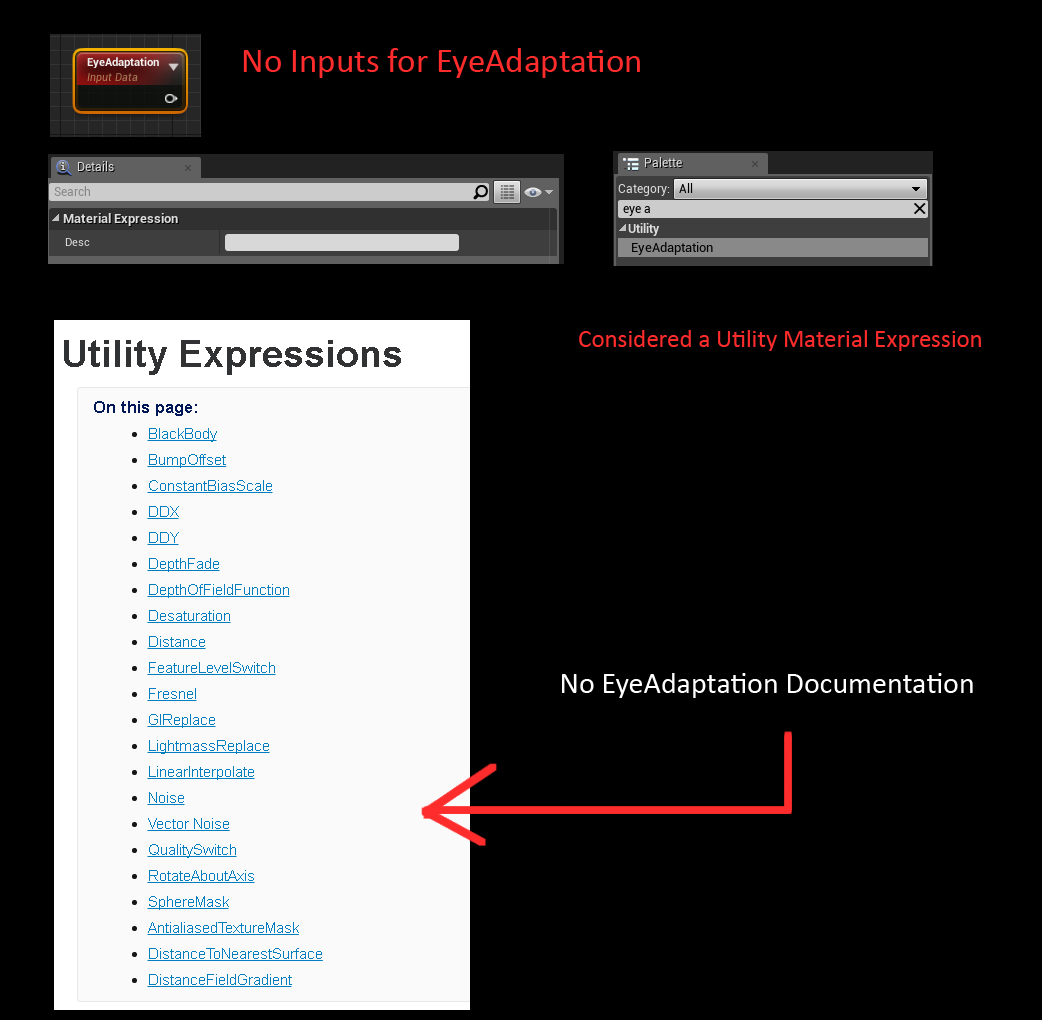
***Note: One of the artists tried to explain the nodes (via comments) but does not specialize in FX. I understand the concept, but not the values and limitations. Specifically Eye Adaptation and World Position Offset.
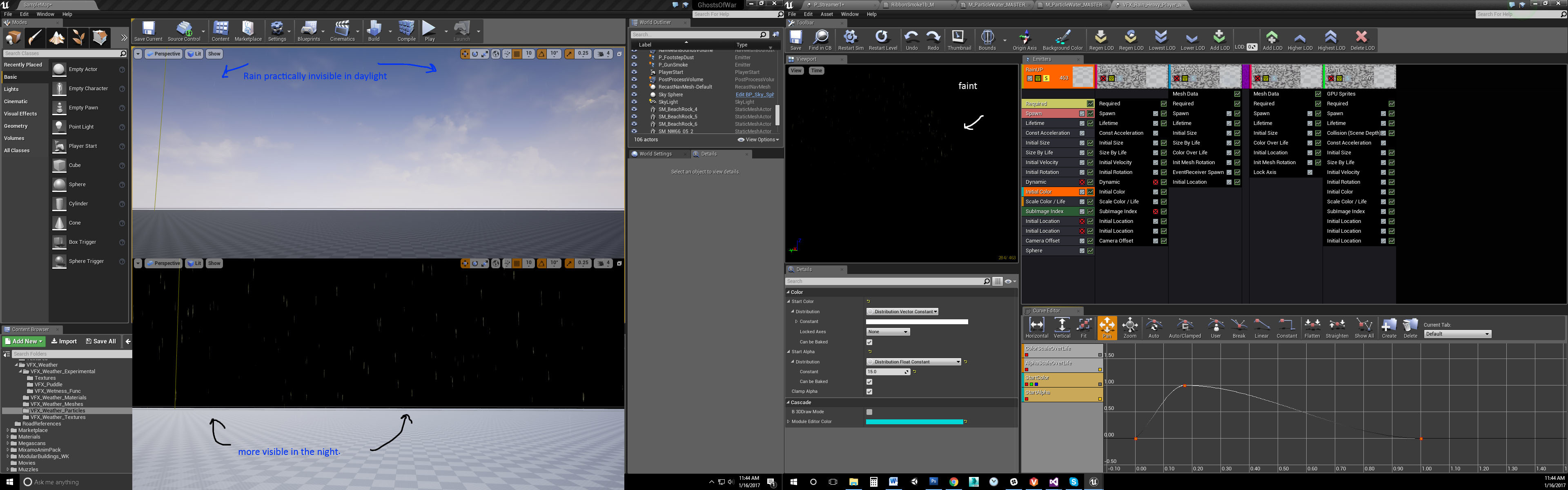
In the first example, you can see the rain is barely visible in the daylight. This is the main problem we’re having. I assumed just plugging an "add" node to the end of the emissive chain would solve the issue (a hacky solution), but I’ve informed that this isn’t the proper answer?
It certainly increased visibility but the concern was that it would also effect night time (to which I said a scalar parameter would most likely scale the emissive value down from 2 to 0 via blueprints during a night cycle). Am I wrong? And if so, is there a better solution?
_____________________________________________________________________
[Image 2]
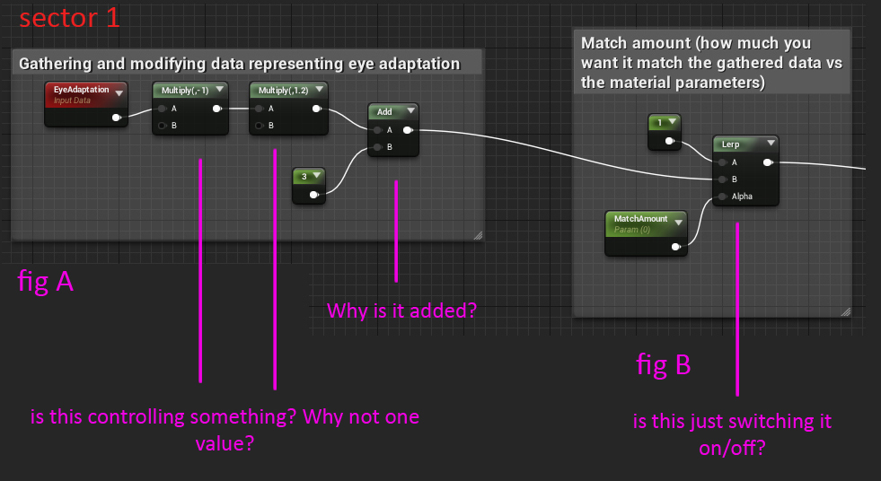
The main confusion here is the “EyeAdaptation” Node. I don’t know what it’s values are and why the previous artist was using two Multiplies and an Add instead of just a flat value. EyeAdaptation has no input values just a description box. I can’t find any information about its use online aside from the PostProcess one here: Auto Exposure in Unreal Engine | Unreal Engine 5.0 Documentation
Apparently the idea was that the rain would be brighter when in shelter/shade, then readjust naturally as you got closer.
Firstly, is this properly set up? Secondly, does this require a PostProcess Volume to see the EyeAdaptation?
Thanks!
2 Likes
If you dont know what values something outputs, try one of the debug nodes, in this case the “debugScalarValues” one would work.
Eye adapt. normally outputs from 0.0625 to 16.0 (1/16th to 16x)
Though, that the output is influenced by post processing.
You dont need a post processing volume to see it, its automatically enabled. you can disable or tweak it in post processing volume though.
Additionally, not sure why there is a camera offset setup in the shader, when there is a camera offset module in cascade.
(granted, its not usable for gpu particles)
I am also giggling a bit due to all the innitial location modules im seeing.
one proper set up cylinder location would be enough.
one last thing I can say within my knowledge, is that additive takes whatever is behind it into consideration… so if a particle is really dark its actually barely visible.
Ok, you lost me on the debugScalarValues. I’m a beginner after all, haha. Do you just plug the EyeAdaptation into the Numbers input then plug it into the Diffuse? I see numbers within the function.
Ok, so the values are very low (below 1) to extremely bright (beyond 2). Does this node serve a use in the material? Can the rains min/max brightness and darkness adaptation not be controlled through the material? By what you’ve said it looks like the post process has control over everything including the rain.
It looks like the camera offset is there for the GPU particles as a Material Instance. The GPU particles are referencing instances and the WPO appears to be set to -50. So that must be what’s pushing the rain away like the CPU. That makes sense actually. Now I’m getting it! Haha.
Ok, I figured a sphere or cylinder would be suitable for the rain. I was lost on the Int Location as well, not sure what the intent was (aside from setting the Z axis higher because the rain is attached to the player).
Alright, so was my solution correct? It does appear that the Cubemap is making the rain material darker. Cubemap is for fake local reflections correct? Would a blue-print controlled scalar parameter (emissive value) be the best solution to combat the dark cubemap or is it more complex than that? Apologies for so many questions, I’m trying to grasp the concepts.
Yea, plug it into the numbers value, and plug that into diffuse/emissive and place the material on a cube.
It does serve a use in the material, it apparently makes the rain brighter when the eye adaptation is darker.
The value is clamped at the end to make sure it never gets too bright.
You could opt to change the brightness depending on the lighting in the level (this gets a tad harder to do in dynamic day/weather) inside a blueprint controlling a dynamic material instance. but if used properly there is nothing wrong with using this setup. (no clue how many instructions it costs)
Your guess for using the camera offset is as good as mine, though I personally doubt how much additional oomph it adds if you spawn at proper locations.
Yea, the cubemap is for fake reflections, and again not sure how much it adds… I tend to not use it and still get decent results, you could see how it looks without it and perhaps replace it with a scalar value.
btw, try changing the background color in cascade, perhaps the rain is easier seen with a grayer/greener background.
Gotcha.
Okay, I still don’t fully understand EyeAdaptation and it seems to work in some strange manner. I made a video below just isolating the EyeAdaptation and trying different combinations with the nodes. Maybe the first multiply sets the base range and it increases to the second one? Yea…
Can you explain what the two multiplies and add are doing? Why isn’t the value flat (i.e. a multiply and a scalar paramater/constant)?
The cube vanishes when the brightness sets in, but reappears when looking at the horizon. When bypassing the two multiplies, it just brightens the cube. Perhaps that is the best solution since that seems to be what we’re after (I can’t recall seeing rain brighten/dim before).
I take it “match amount” just means whether the effect is on or off. The description threw me off for a while but its just a scalar parameter.
Apparently when just plugging in a flat value into the diffuse (no EyeAdaptation node) it does the same thing as bypassing the multiplies…So it looks like the multiplies are actually making the cube vanish and the EyeAdaptation node doesn’t do anything. I recall that the brightness/dimming is Auto Exposure. and can be turned off through a PostProcess volume.
What’s the purpose of the EyeAdaptation node if the Auto Exposure is what’s brightening things globally? It seems to be negating any visual cues the EyeAdaptation node in the material would show.
The aim here is: Increase daytime visibility of rain and keep eye-adaptation. Most likely drop the cubemap since it’s too dark and reflections are hard to see anyways (rain’s fast and small). I keep asking about the EyeAdaptation because I want to know how to alter it if necessary. Right now it’s stuck at whatever value the previous artist left it at.
https://www.youtube.com/watch?v=JKgXLosIs_E&feature=youtu.be
Sector 1:
The Multiplier (-1) inverts the value of the eyeadaptation. (not sure why they didnt use a regular oneminus node)
so if the value was 16, its now -16
multiplying that with 1.2 results in -19.2.
then 3 is added to make… dun…dun…duuuun… 16.2
this obviously would change quite a bit depending on the initial value. 1 would be -1 > -1.2 > 2.2.
the match-amount is probably to blend between just the regular 1 value, and whatever the eyeadapt-setup controls.
I think the goal here is to try and find a way that in very dark situations the rain is still visible in both dark and light scenes regardless of how much eye adaptation is going on. (darker when its bright, brighter when its dark).
I think the multiplier of 1.2 was just a guess by the previous guy.
Thing is, without extensive trying or knowing the exact thought about it… it might be fairly hard to get it to work right.
Hmmm, that’s interesting. This is some strange logic going on (between the multiply 1.2 and Add 3). I don’t get why you can’t just have an add with .2 if the result was supposed to be 16.2. The setup and logic seems off to me.
Based on the documentation the range would be -2 to 2 at max (in regards to PostProcess). So if 16 was the base value of EyeAdaptation, then it would be: EyeAdaptation > Divide (8) > Lerp > Diffuse Input
I guess the 2 would be the highest range in brightness? Based on what you’re saying, it seems that the 2nd multiply (1.2) determines the Low of EyeAdaptation, and the Add (3) determines the High of EyeAdaptation.
I checked the documentation again and didn’t find anything about this “Material Expression.” or how to set it up. It looks like almost no-one uses it within the material and I assume its purpose is to manually alter the default values within the world.
You said I don’t need a postprocess volume to see it (Auto Exposure is enabled by default). So would I require a PostProcess in order to tweak the values? Wouldn’t that be a global change instead of an isolated one (i.e. everything becomes the range instead of just the rain, which would make the material expression void)?
I’ll keep testing it but If I don’t know what the inputs are or how the expression setup works I wont get very far. If I’m missing something obvious I apologize, this node is tripping me out haha.
Ok, we seemed to have made sense of what the EyeAdaptation setup is doing. As you said before Luos, the range is .6 to 16 (depending on the PostProcess range).
If the PostProcess (or whatever is controlling the default Auto Exposure) is set Min Brightness: 0 and Max Brightness: 2, then the values will be clamped from 0 to 0.6. Basically the PostProcess/Auto-Exposure is communicating with the node within the material then filtering it down for the rain specifically.
The equation would be: Eye Adaptation (Max Value 2) x -1 x 1.2 + 3 = 0.6 which is then Clamped (0-1 range).
It appears the idea was to establish a clamp that would remain no matter what Max Brightness there was. The clamp kinda negated the math in some ways since it can only reach a maximum of 1.
Neat.
Alright, so I’m setting aside the rain for now and focusing on other FX.
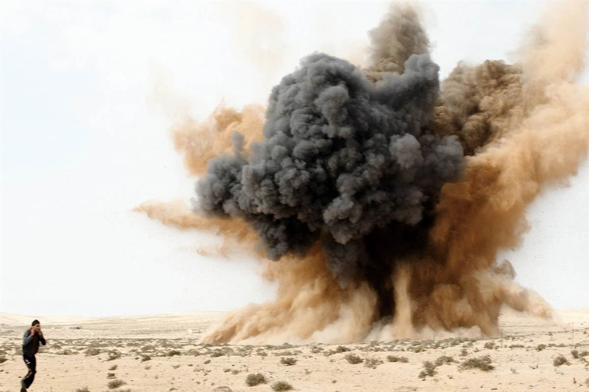
I have to create an Armor Piercing (AP) round and a High-explosive (HE) round hitting terrain and wanted to know the limitations of Cascade and whether or not I should simulate the entire FX.
It looks like Emitter Init Location would be the go-to for something like this since it’d follow the main particles then pause momentarily. But it looks like the problem would be the spawn since it gets patchy or over spawns when the spawnrate is fixed but the leader particle isn’t. (Image 1)
Ribbons will just make it look like a streak and there’s some known bug that causes them to snap back sometimes.
I was hoping to make it real-time but it looks like simulated would be a better choice, although it would make the main explosions all look the same. Any ideas where I could find a FumeFX tutorial on Dirt explosions? I mostly see fire and smoke around.
1 Like
Those types of explosions are incredibly cool, and also incredibly hard to make. Unless you are a simulation god, don’t go the fully simulated route, and if you are: Do you really want the effect to look the exact same every time? And how will you handle slopes? Buildings? Different materials?
Some pointers:
Make it from many different emitters with different shades of smoke.
Stock footage is often a good starting point for the super shaped ones. However, if you do go down the simulation route, look into emitting fluids from particles. No idea how to do it in fume, but that’s the way you do it in most packages.
Only use ribbons if you can afford the particle cost and desperately need the arcing. A nicely animated stretched sprite goes a long way. Hell even a bent mesh with a scrolling texture can work sometimes.
The spikes need to be superfast or they will look weird.
Don’t forget the grounding effects.
Light stuff at the top, heavy at the bottom.
If you add fire, make it only a couple of frames. No more needed.
Don’t forget the secondaries.
1 Like
Ok, I’m new to the simulation stuff, so it seems like that’s not a good solution. I’m more used to manipulating static textures.
When you say stock footage, do you mean as reference or as an actual texture?
If I understand correctly you’re saying use static images (stretching/scaling up) in combination with secondary emitters (smoke trails/debris/etc).
I notice that the FX in these tank games are very quick and simple. Armored Warfare is more recent and it’s using static textures for stuff like water explosions from what I can see. (2:34) It looks like the mentality is “use sims/flipbooks where necessary” since that would hamper performance.
I was looking at this old CoD gameplay (6:45) and it looked like the optimal route. It’s certainly the cheapest since its just a small initial blast then there’s a single smoke cloud texture stretching upwards (very short lifetime), some lingering smoke and a bunch of debris particles falling (3D by the looks of it).
Don’t forget the grounding effects.
Light stuff at the top, heavy at the bottom.
Don’t forget the secondaries.
I vaguely understand what you’re saying. Is this in regards to sims or real-time? I’ll be using half and half, primarily a static texture stretching for the smoke part. The secondaries are the smaller details right?
I use stockfootage as the base for many of my textures. It’s really quick and usually gives decent results.
If you are making games for handheld, or old gen, quick effects are the way to go. Me personally am allergic to effects that instadisappear. We have the power now. Look at ref 
All pointers where realtimey.
Grounding effects are the stuff you spawn along the ground so you don’t end up with a freefloating smokepuff.
Light stuff at the top, heavy at the bottom = Heavy debris and thick smoke at the bottom, small debris fly far. Very simple concept, but very easy to forget.
Secondaries: Raining debris, lingering smoke, camera shake, screen effects and so on.
Hmmm, so it seems there’s limitations on both ends. Here’s what I understand so far:
Simulated
- Looks great but costs more and will always look the same (flipbook/SubUV)
- Cannot be used on slopes, looks best on flat terrain
Real-time/Static
- Controlled Dynamically by Cascade
- Looks okay, cost less and has some variety (shader tricks)
- Can adjust to terrain dynamically
Combined
- Controlled partially by Cascade
- Looks decent, cost is moderate to low (depending on what’s using a flipbook)
- Only good for explosions/smoke sims that are spawning from a circle/center
I’m using the combined route atm. The ground explosions are probably best made as static stretched textures and the secondary (lingering smoke) using the pre-simmed stuff. Maybe throw in some shader trickery like an alpha dissolve to fake the dispersion.
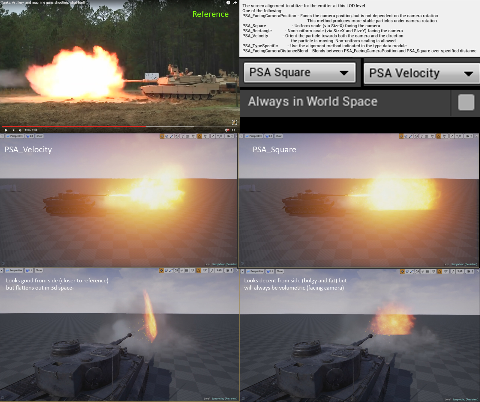
Here’s something I noticed about the screen alignment modes as well. It’ll look closer to the reference using PSA_Velocity and face the right direction, but flatten out in other views. Using PSA_Rectangle will just cause the stretching to face you and will look wrong.
PSA_Square will look bulgy but be volumetric since its always facing the camera. Yet another trade-off it seems.
.
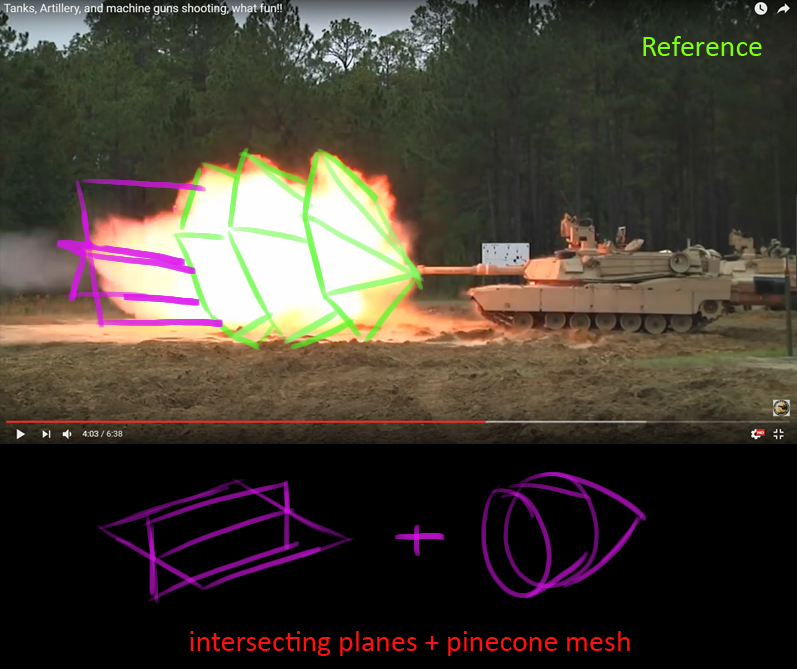
Muzzleflashes won’t work with just one sprite. You either need to build a flowermesh or emit one velocity aligned sprite that’s visible from the side, and one square that’s visible from the front. Preferably multiple sprites, but one emitter of each type so to speak. Especially for a huge flash like that of a tank.
Yea, I remember that muzzle flashes are 3d (Luos’s videos). I should’ve realized that for the tank. Thanks for the reminder haha.
So you mean something like a pinecone mesh? My solution would be a couple of pinecone planes and some intersecting/crossing planes for the tip. A point wouldn’t work since the edges are frayed. This would probably look alot better than trying to overlap two types of screen alignments.
1 Like
Yes, that\s the sort of mesh I was talking about I haven’t used them in a couple of years though. Muzzleflashes are so damn quick it’s often quicker and more dynamic to use sprites with different alignments. We are talking 3 frames here, tops.
But both techniques are absolutely viable. Sprites are just my personal preference.
Okay, is it possible to have PBR materials but enable opacity? I want the model to be opaque with metalness/roughness/etc but be able to fade out over its lifetime. It’s for a “Nail Construction FX” where the nails spawn then fade out quickly. It’d be nicer than just some flat gray metal texture.
I went through the lighting modes and the choices were either Surface TranslucencyVolume or Surface Foward Shading. They also don’t cull the back faces.
It looks like the lighting model was renamed and acts differently as well. The image below is what looks to be the answer but its from an older build.
How can I get a similar result to the video (Time: 2:34)? I want the smoke to burst out then linger for a couple of seconds before the wind carries it away. I’m having trouble getting the emitter to work right.
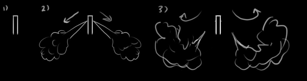
In [number 1] you can see that I tried to scatter the smoke initially, which is incorrect. I want that result towards the end though.
In [number 2] you can see I tried to make it jet out, but it turns into a cotton ball and doesn’t scatter. I’ve tried using a constant curve to force it to scatter over its lifetime with sphere/cylinder (location), but it didn’t work.
In my mind, the order of operations should be:
- Start with Size by life and scale over time to create a cone shape
- High Velocity/life with Drag so that it fires out instantly and slows down immediately
- Have it spread out using a cylinder modifier over its life (prevents cotton ball)
- Acceleration over life- Have it low while it lingers before speeding up towards the end
It’s like the burst is competing with the long lifetime or something. Perhaps I need a vector field for all of this?
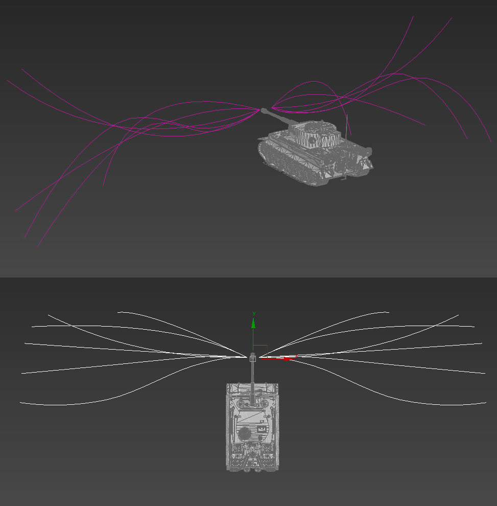
Hmmm. This feels like the closest I’ll get to the smoke behaviour (video). I want it to scatter once its fired out, but the Vector Fields aren’t working like I though they would. I’m using the VF Shapes plugin for 3dsmax.
One would assume the smoke would come out like the second image below. Kind of spread out in a cone as it scales up over life. I can’t even tell what direction the Fields are going within UE4 since its “dashes” instead of “arrows”.
In the first image I did a test to see the directions of the particles. I get a different behavior in UE4 and it doesn’t even follow the splines (Tightness set to 1.0). Has anyone used the VF Shapes tool before?
https://www.youtube.com/watch?v=JzwjHmiAcAc&feature=youtu.be


")