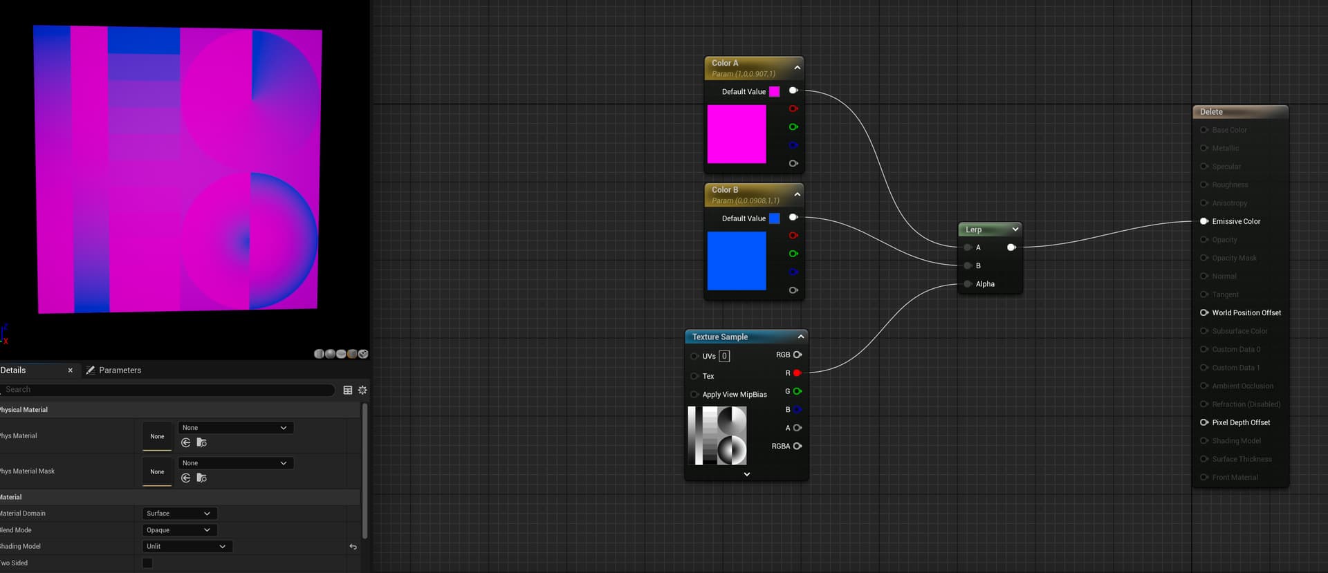
Zoomed image
I just had an idea, what if I put two Additive materials together in a Material Graph?, no wait that might be dumb. I’m trying to think outside the box now.
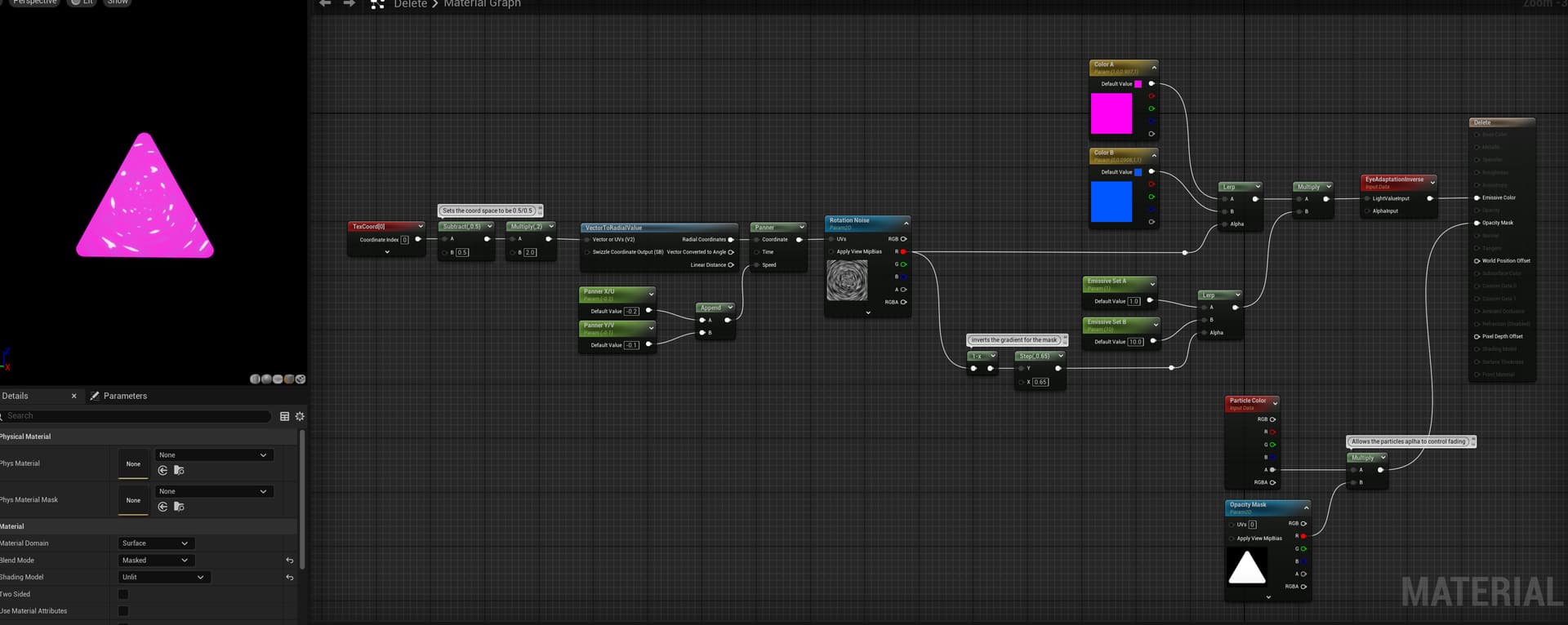
What you’re wanting to do with the red and pink, should be done with a LERP.
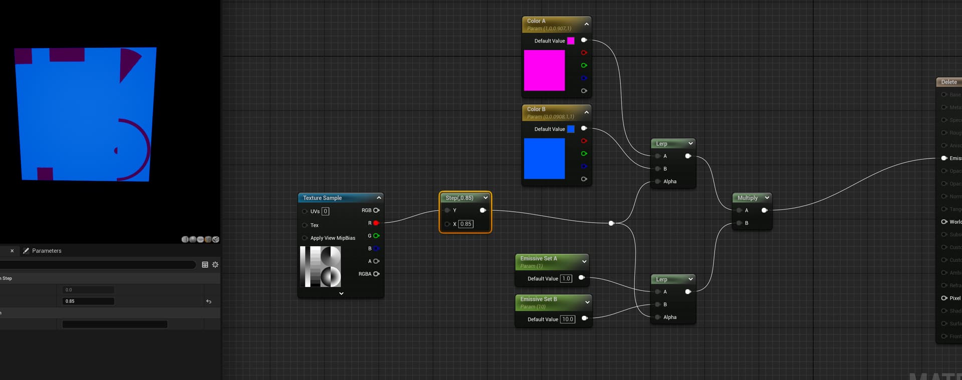
Here is an example of a Lerp working with multiple black and white levels. You can see how the black/gray/white value in the texture blend the blue and pink color.
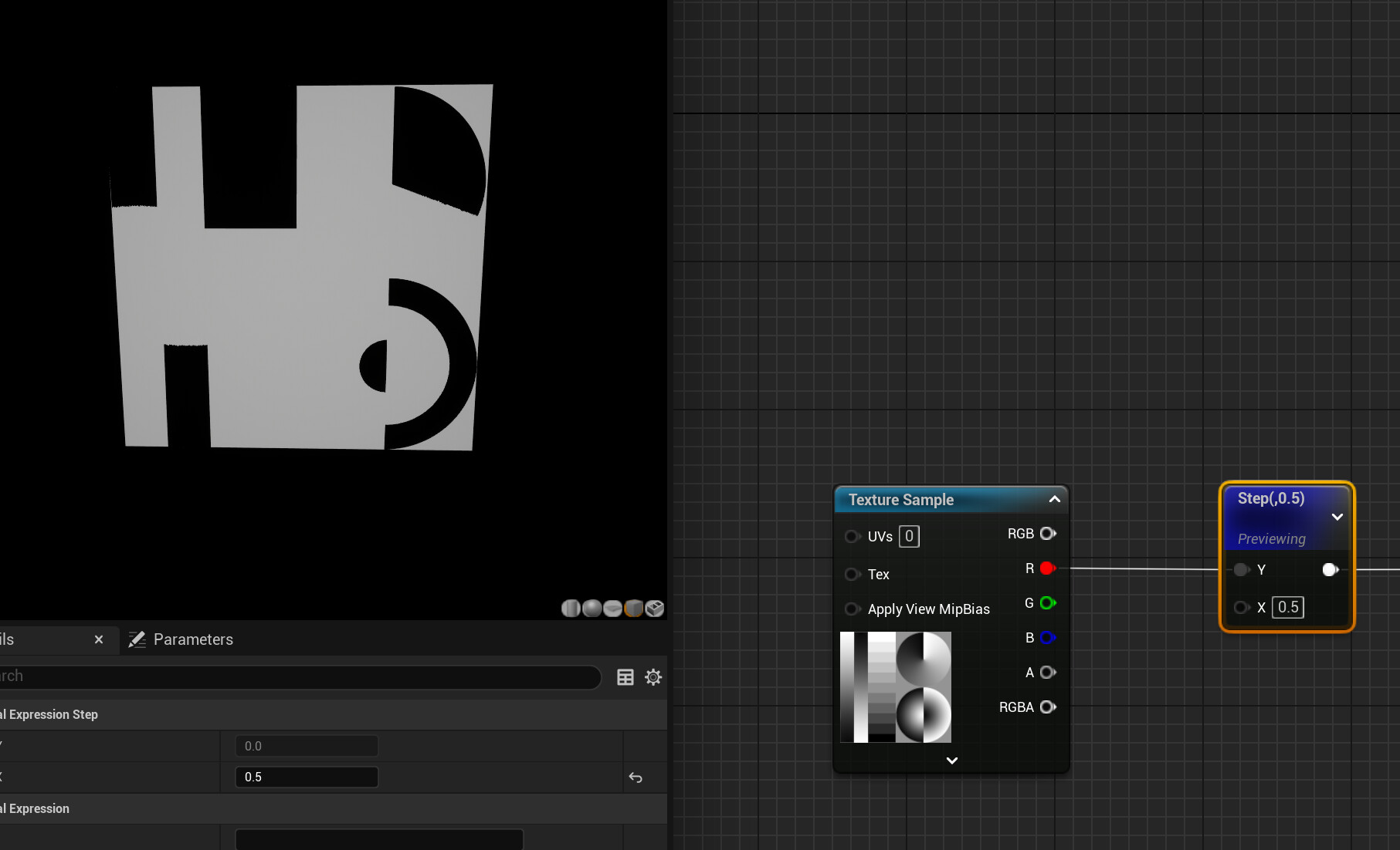
If you wanted to have more control over the intensity of each section you could do this as well, by adding a step node to a seperate LERP.
A step node, set at a value of 0.5
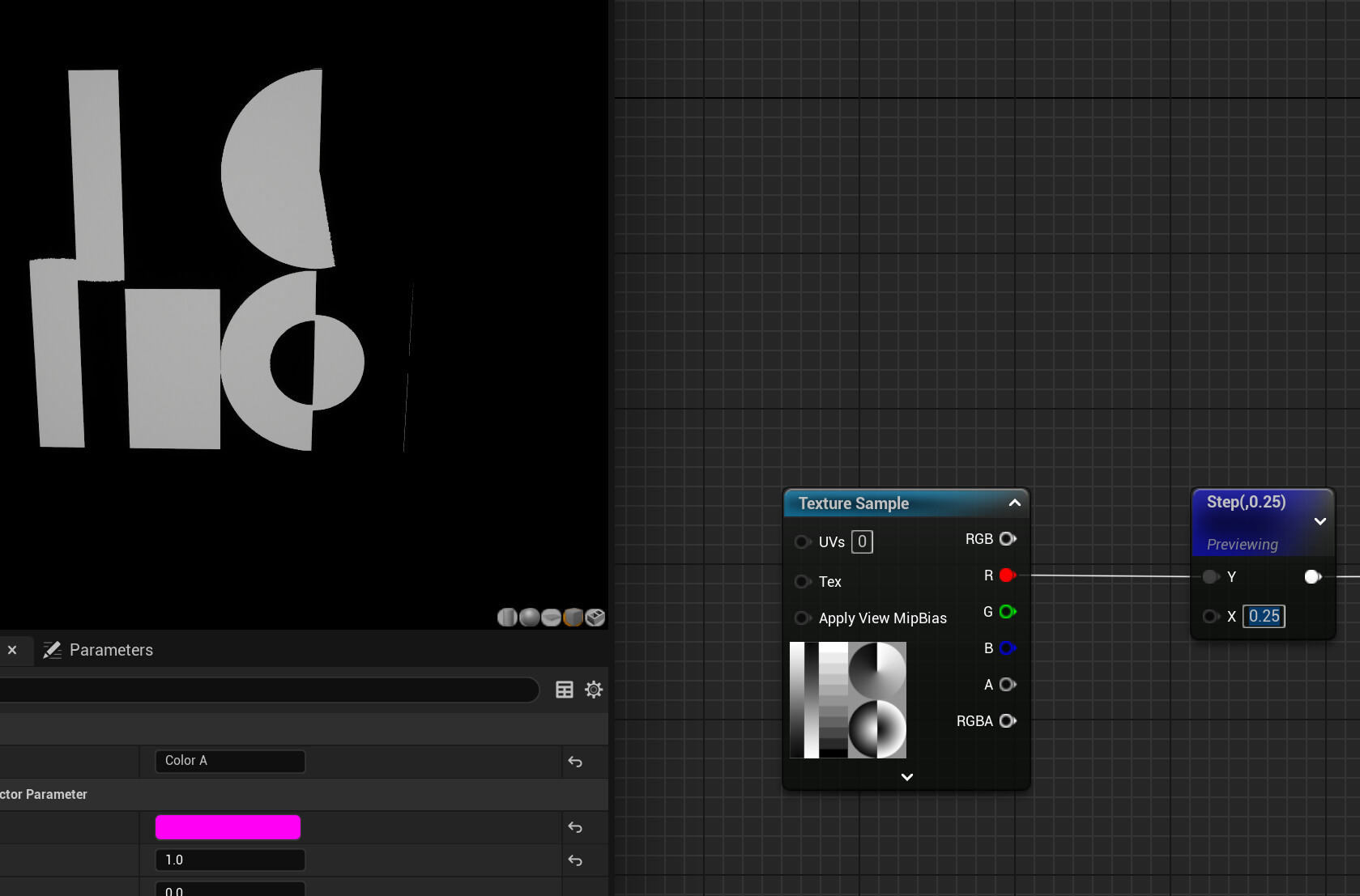
A step node, set at a value of 0.25
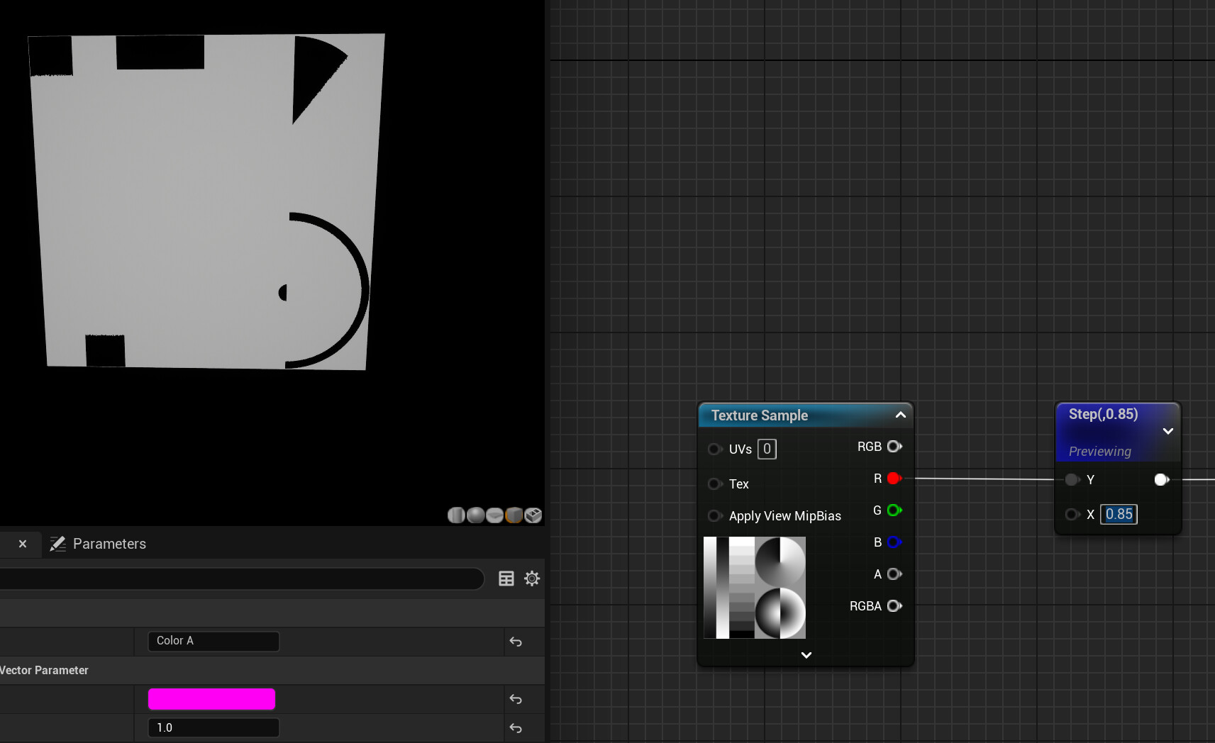
A step node, set at a value of 0.85
Hopefully you can see the “Step” node is a mathematical expression that outputs either 0 or 1 based on whether the input value is greater than or less than a reference value.
This is now acting as a mask for the LERP, in which you can now pass seperate values for the red and pink to be emissive.
I hope this makes sense.
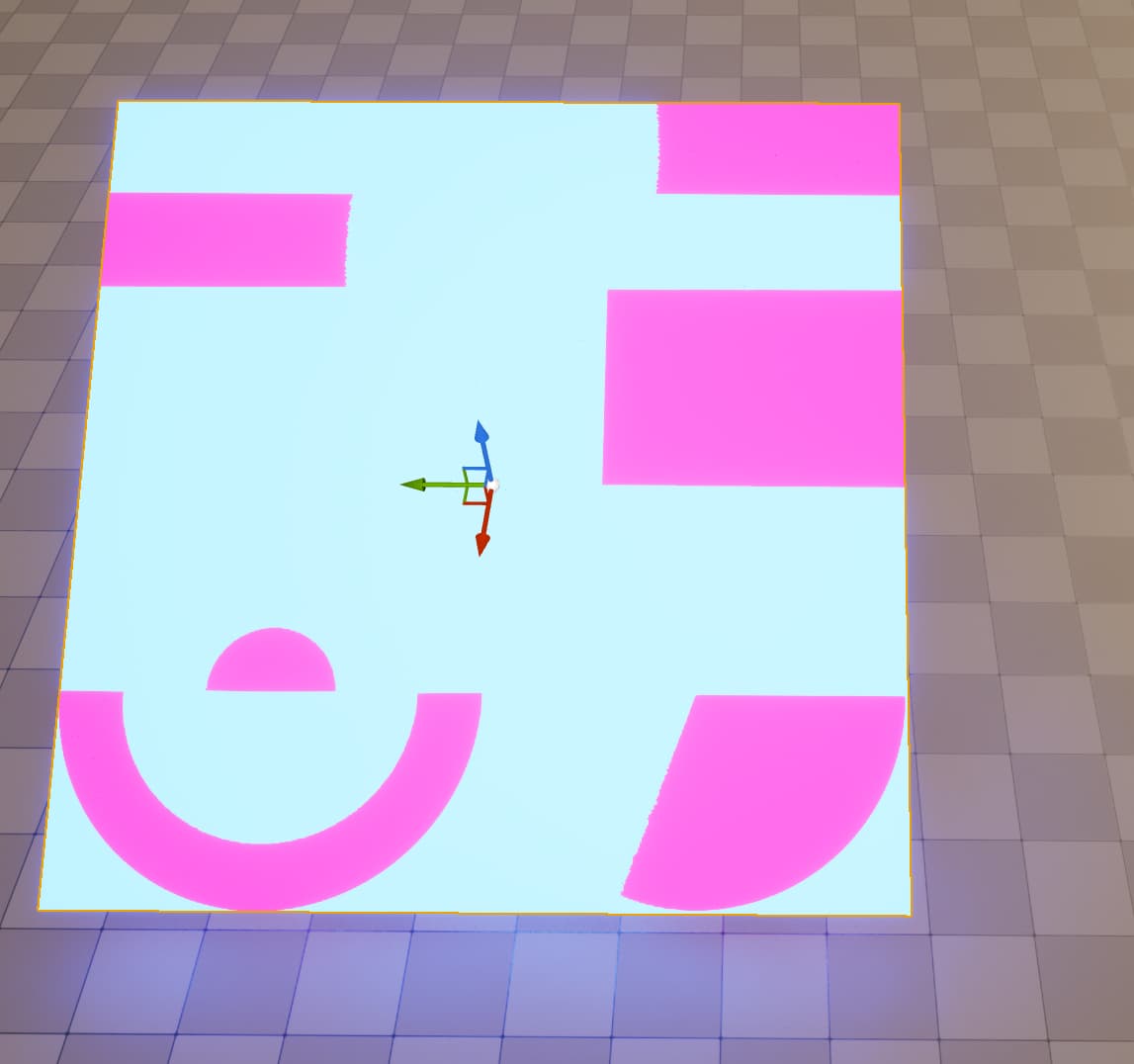
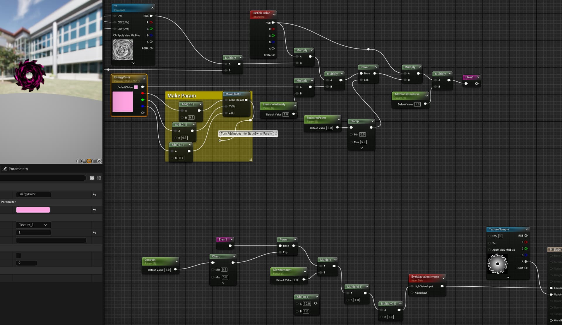
Youre material could be as simple as this.
Take a moment and ask any questions that you might have on how this material was created. You shouldn’t have to use a DDX/DDY function slike you had in your material.
1 Like
Yes this is the method i was looking for, i will evaluate my material and see where to input this. Thank you. I also never thought to use lerp for a mask but thats a neat trick.
OK. so I updated material and maybe this is a better final representation of what I’m looking for. The fire is orange but has varying tones of red, yellow, and orange.
The black is supposed to be black for this fire material.
But say I want an electric material that is Blue where the orange part is and Yellow where the black panning left part is.
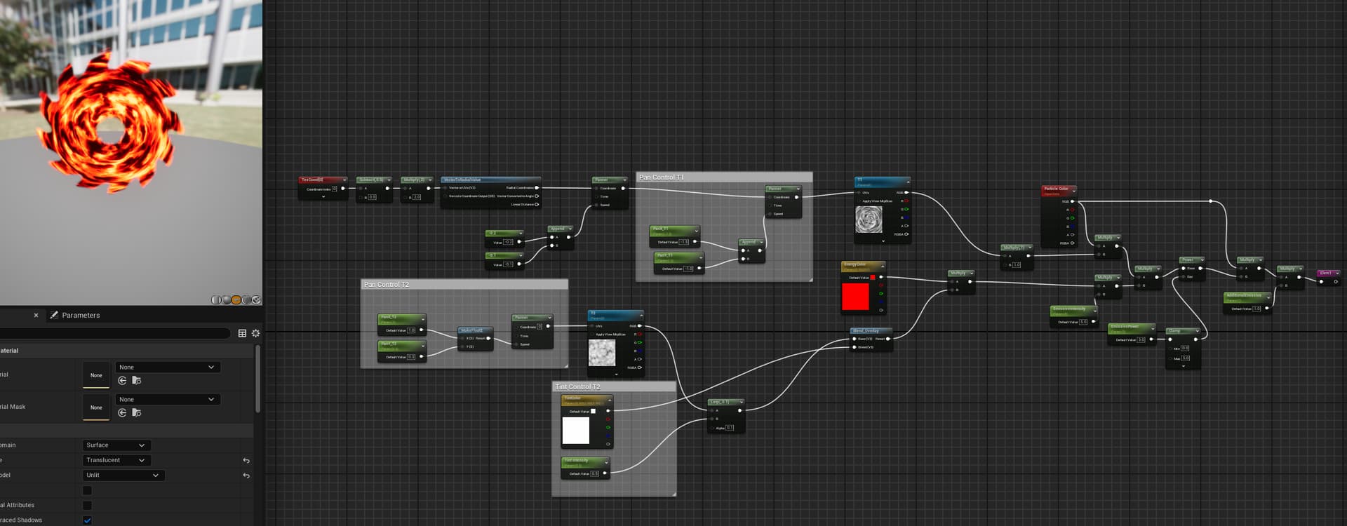
I also just realized that even if I disconnect the Blend overlay, the orange part still has black in it. I want both the black parts of the 2 textures to sync together as a color choice, so ex I could change the black to be red if I wanted. I know i keep saying things over with diff examples, but I sometimes myself don’t understand one way someone asks me so i figure I would just clarify any confusion with multiple examples.
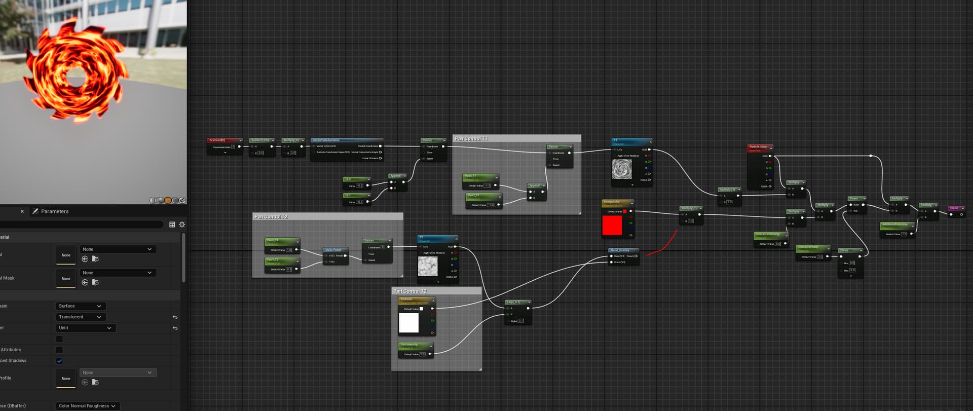
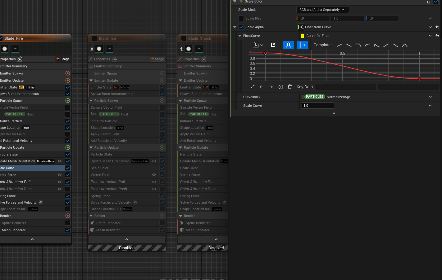
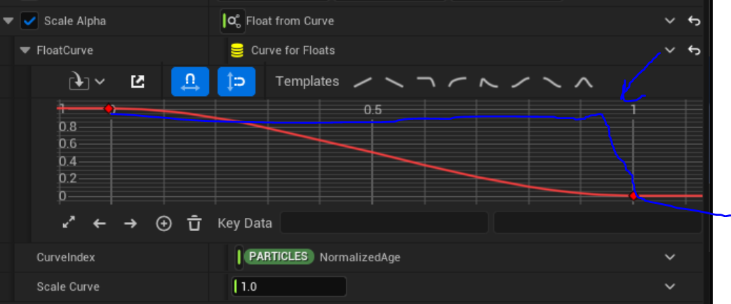
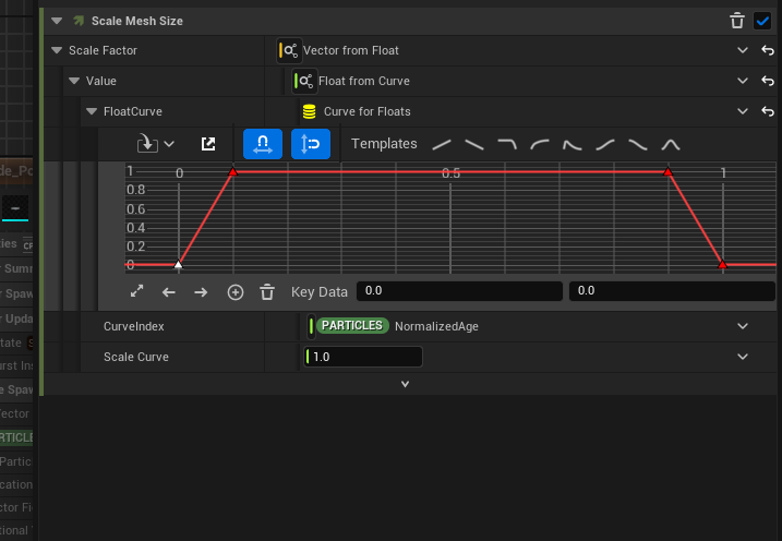
This is my Opacity. I id the opacity method u showed, but it made the blades continually fade out over time, and I only want them to disappear at the end of their lifetime. They should be full opacity the who emitter duration and then I have them fade out and shrink over at the last .2 seconds.
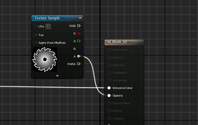
I’m not sure if you ment to add an image here or not.
What does your niagara sysyem look like? Sounds like you have an update in your particle color with the normalized age of your particles setting your fade time.

sorry, i had adjusted it properly on my other version I made but they move randomly with a vector field. I can do the same real quick on this one.
So then I’d hook up the particle color opacity to multiply with your alpha to let the particles fade in/out
sweet that works. It now fades the mesh properly with the Niagara System./ Wait i used wrong master. I need to try with correct one. Ok still works
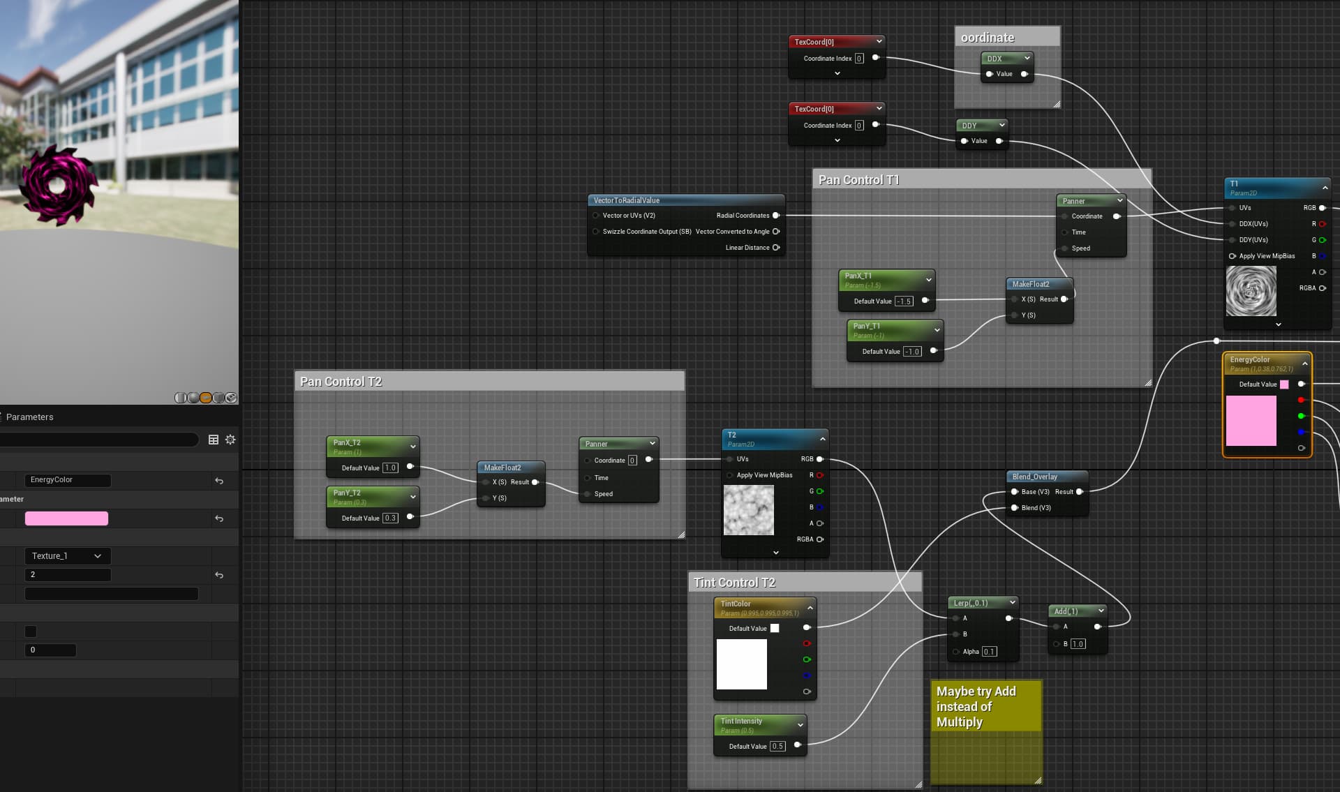
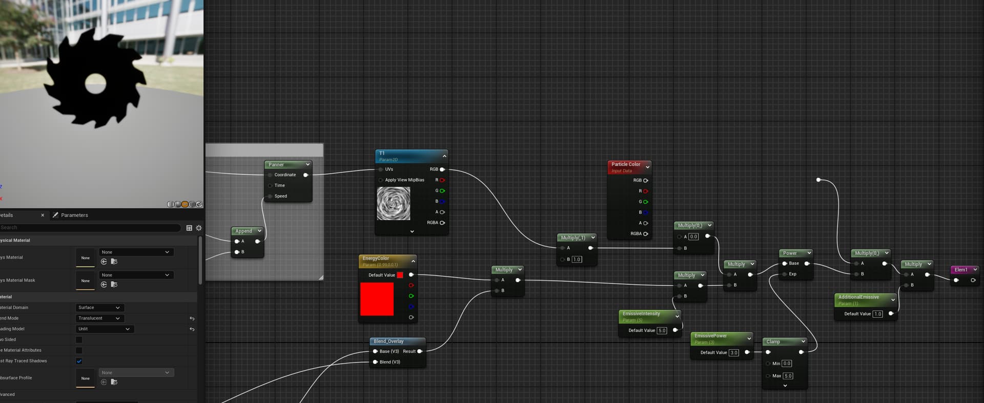
I have question about what your intention here is:
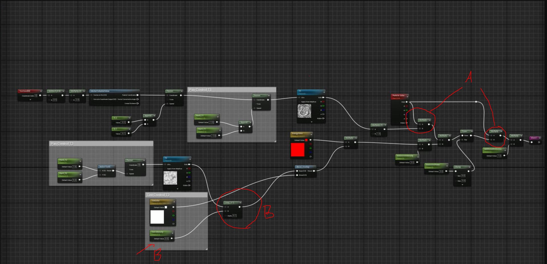
A: why do you have the particle color multiplying twice? Also, Why are you adding color in both the material instance and in the niagara system? Why not just have it set in one place or the other? If you wanted to have the particle color act as a “tint” that would make sense, but otherwise, not sure what youre doing here.
B: You have a “tint intensity” going into your B slot of your lerp and a static set value of 0.1 in the alpha controls. Might I suggest you add the “tint intensity” to the alpha lerp control and the set static value in the B slot of the lerp?
I didnt delete the other Particle Color yet bec i made everything black
I will try your suggestion out
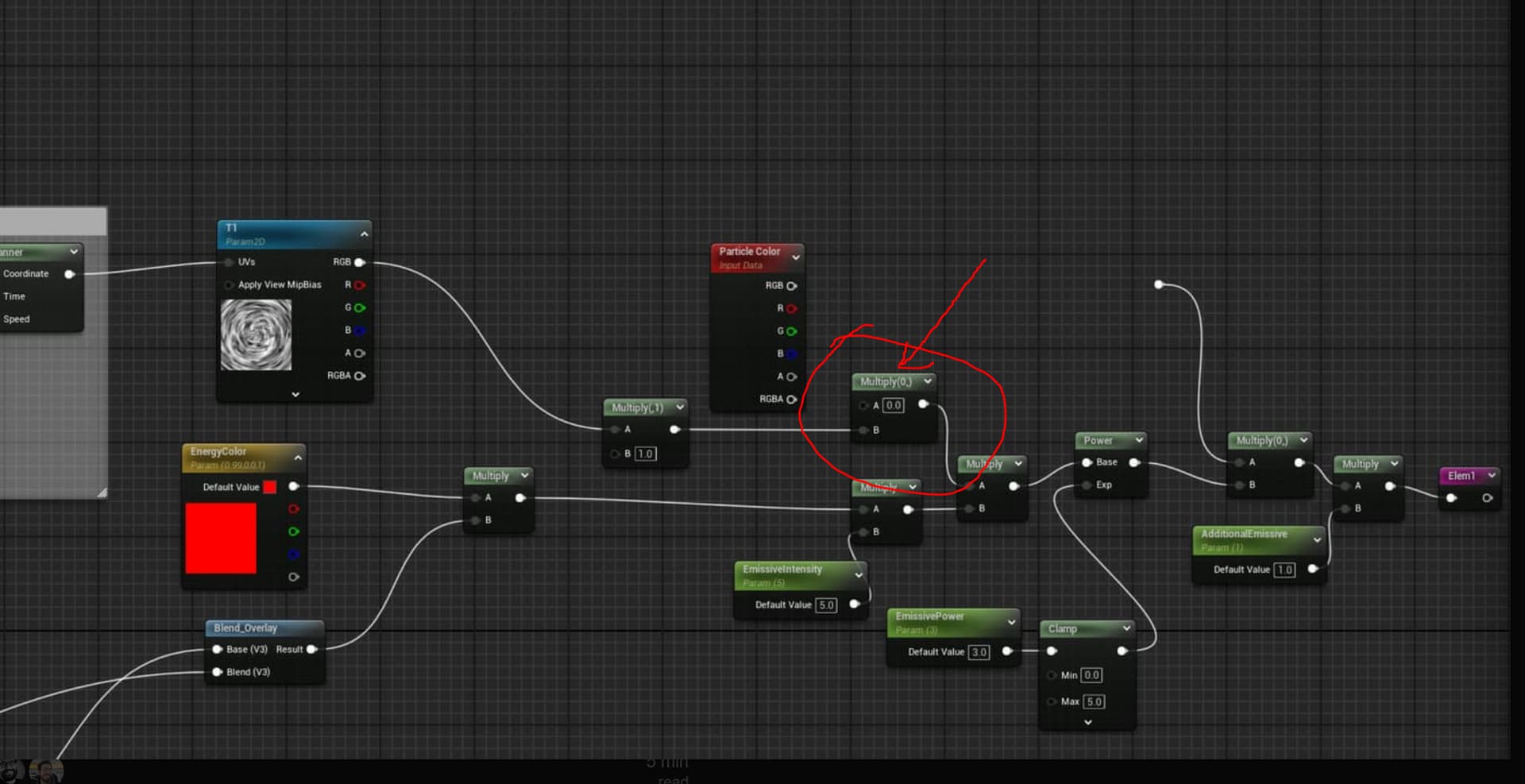
looks better and simpler to navigate. I removed extra multiply nodes
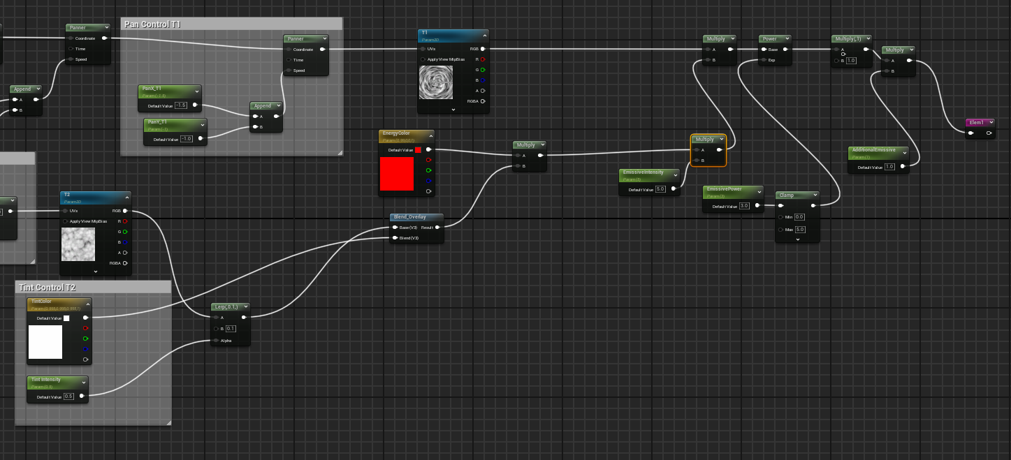
new setup + the Opacity method u showed me
I think thats looking much better as was as you math logic