Tiling a sub uv I seem to get what looks like some kind of padding issue. In this example I’m sampling the first sub uv, which is just a black box, and tiling it. Even though it’s all black I’m getting white edges around each tile. My first thought was some kind of padding thing, but I made the black box bigger than the sub uv and still get those white edges. Is there a way to sample a smaller portion of each sub uv? Would that help?
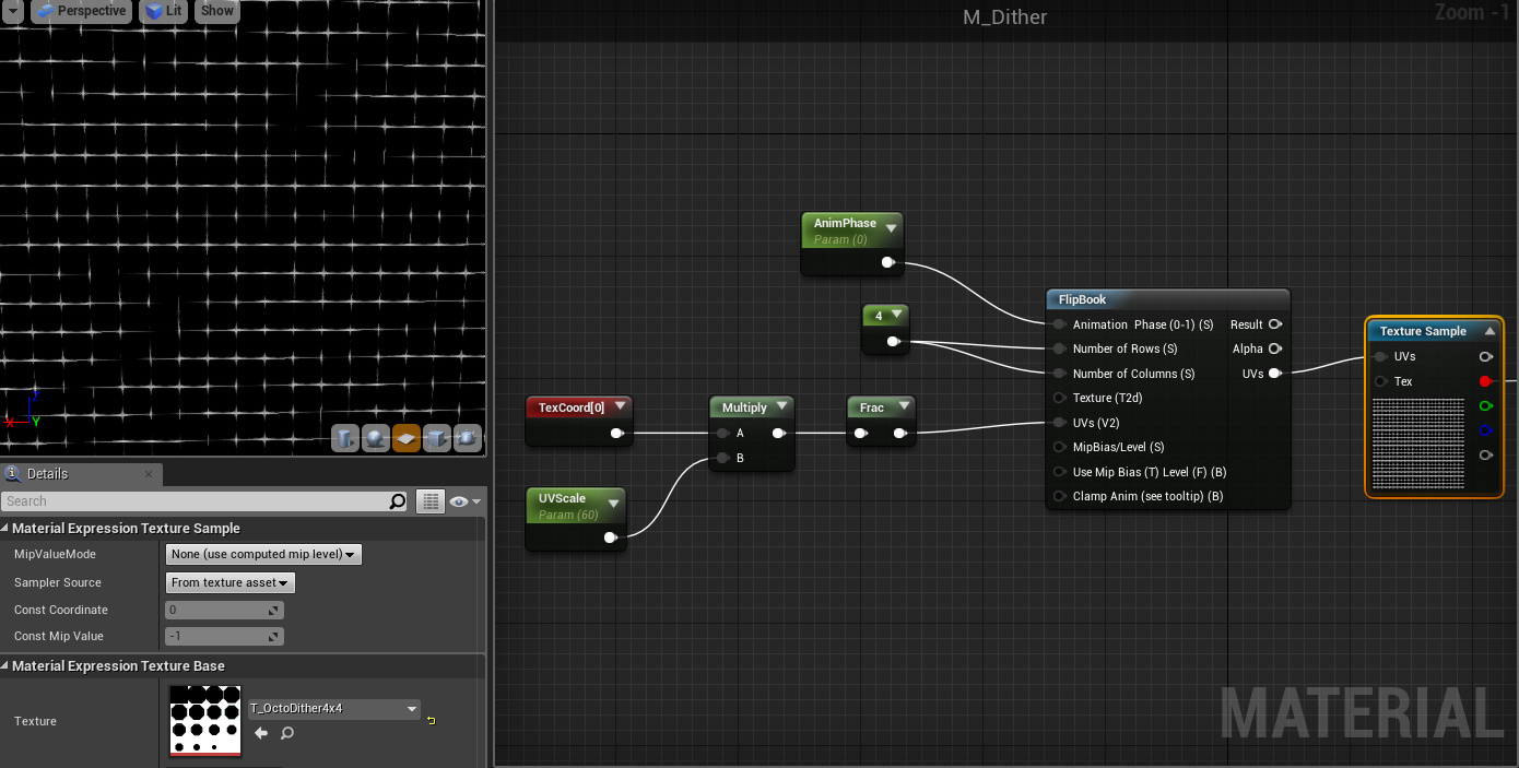
Here’s a screen shot. You can see the texture I’m using in the bottom left. I’m expecting to see all black in the preview, but instead get this screen door kind of effect. Any ideas?
Aha! You fool! You fell victim to one of the classic blunders - the most famous of which is “never use a texture with out proper padding” - but only slightly less well-known is this: “Never use a frac on a texture UV without calculating the derivates!”
GPUs determine the mip level to use for a texture by how much the UV changes between pixels. When you use a frac you’re causing the UV to go from “0.99” to “0.0” in one pixel. That means the GPU thinks the entire texture is being “seen” between those two pixels, and thus it should use the smallest mip available.
There are a few solutions. The simplest one is to disable mip maps entirely on the texture, or manually set the mip level on the texture sample. This will cause aliasing issues if your texture is viewed with any amount of minification (would normally be showing less than the largest mip level).
What you want to do instead is to pass the derivatives (ddx & ddy) of the post-scale & pre-frac UVs into the texture sample.
I believe in UE4 you can select the texture sample node and change the MipValueMode to Derivatives and it’ll expose two inputs. Then make a ddx and a ddy node and input the output of the multiply node before the Frac into those. Then pipe the dd* nodes into the appropriate input on the texture sample node.
Excellent! Thanks for the detailed description. Disabling mip maps on the texture did the trick, which should be fine for where I intend to use it. Plugging in the derivatives worked somewhat. Better, but small dots if I zoomed way in and a flat gray when I zoom out enough. Don’t intend to use it with those extremes but thought I’d report back my findings.
Might have been able to use the dd nodes differently (if that would help the issue), but I’ll have to spend the next few years building up an immunity to derivative use in shaders, as not to kill myself.
Because you’re passing the UVs into the flipbook node which also scales the UVs, you’ll need to divide the UV values by the rows / columns. Since in this case they’re the same value (and constant) you can multiply the UVs by 0.25 before going to the ddx & ddy nodes.
That definitely helped, but still there a bit. Dots are smaller, have to move farther back until goes gray. Then I tried putting in smaller numbers and it improved. Then I just input 0 and that made it work. No idea what I’m doing though, is that just the same as disabling mip maps?
Zero would indeed be the same as disabling mip maps. I suspect what you’re seeing with the mul of 0.25 is just normal mip mapping / padding issues. Remove the frac & derivatives when it’s going grey and I suspect you’ll see the same grey.
The solution to that is super sampling in the shader… Or just disabling mips.
a possible low-fi (and probably slightly more expensive) solution would be to just create a edge mask texture and tile that as many times as you need and multiply over the top.
another texture look up (unless you put the mask in the alpha) but i’ve no idea how the two sets of maths would compare cost wise.