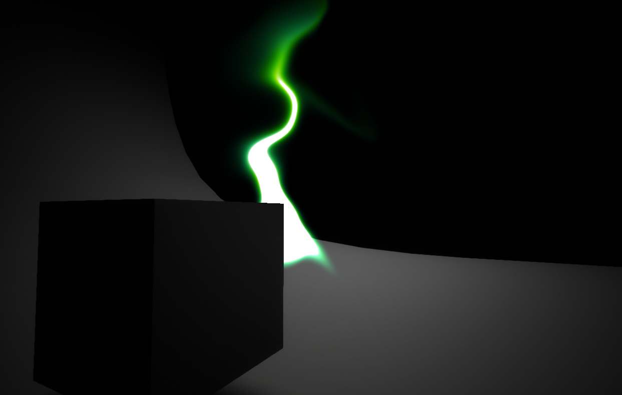
Okay, after getting a few requests for a breakdown of this I finally got it organized enough to (hopefully) explain. Here’s what’s up.
The base idea is: given some world position you want as the “source” of the smoke, every frame, you project that position into screen coordinates and draw a glow at that position into a render target. Then you use a post-process material to composite that target into your camera view. There’s a few more wrinkles that you have to address, including some I never got around to working out:
- distorting the smoke so it looks like it’s being blown around
- fading it out over time so it doesn’t just fill up your screen
- color variation
-
(unaddressed) accounting for camera movement / rotation to make the screen-space-i-ness of it less obvious
-
(unaddressed) hiding it behind objects
Here’s the entirety of the Blueprint part of this. I’ll explain the details below.
In the upper left, you can see the logic for transforming the position to screen space, as well as a sketchy way to figure out a screen-space size (the distance between the screen-space projections of the main point and a nearby point the-world-space-radius away from it).
Note that there are two separate render targets: a “scratch” target that most things are drawn into, created dynamically elsewhere in this blueprint, and then a final one that’s a named asset (WarpRenderTarget). I think the only reason for this is that I couldn’t figure out how to access the post-process material from a blueprint to give it the scratch target. The render targets are both RG16F—the red channel is the “density”, where the smoke is, and the green channel is a color mix value. The actual color is applied at the end by the post-process material.
Here’s what one of the render target looks like after a while; the yellow area is where there’s some red (density) present, while the green is color-mix value that’s been swirled around over time.
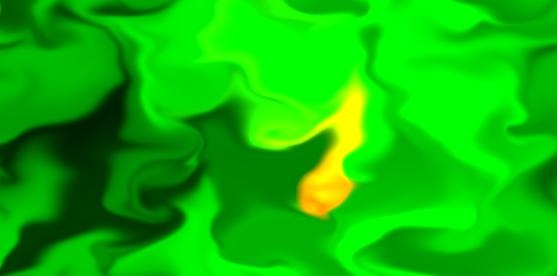
–
In sequence, here are the materials in use.
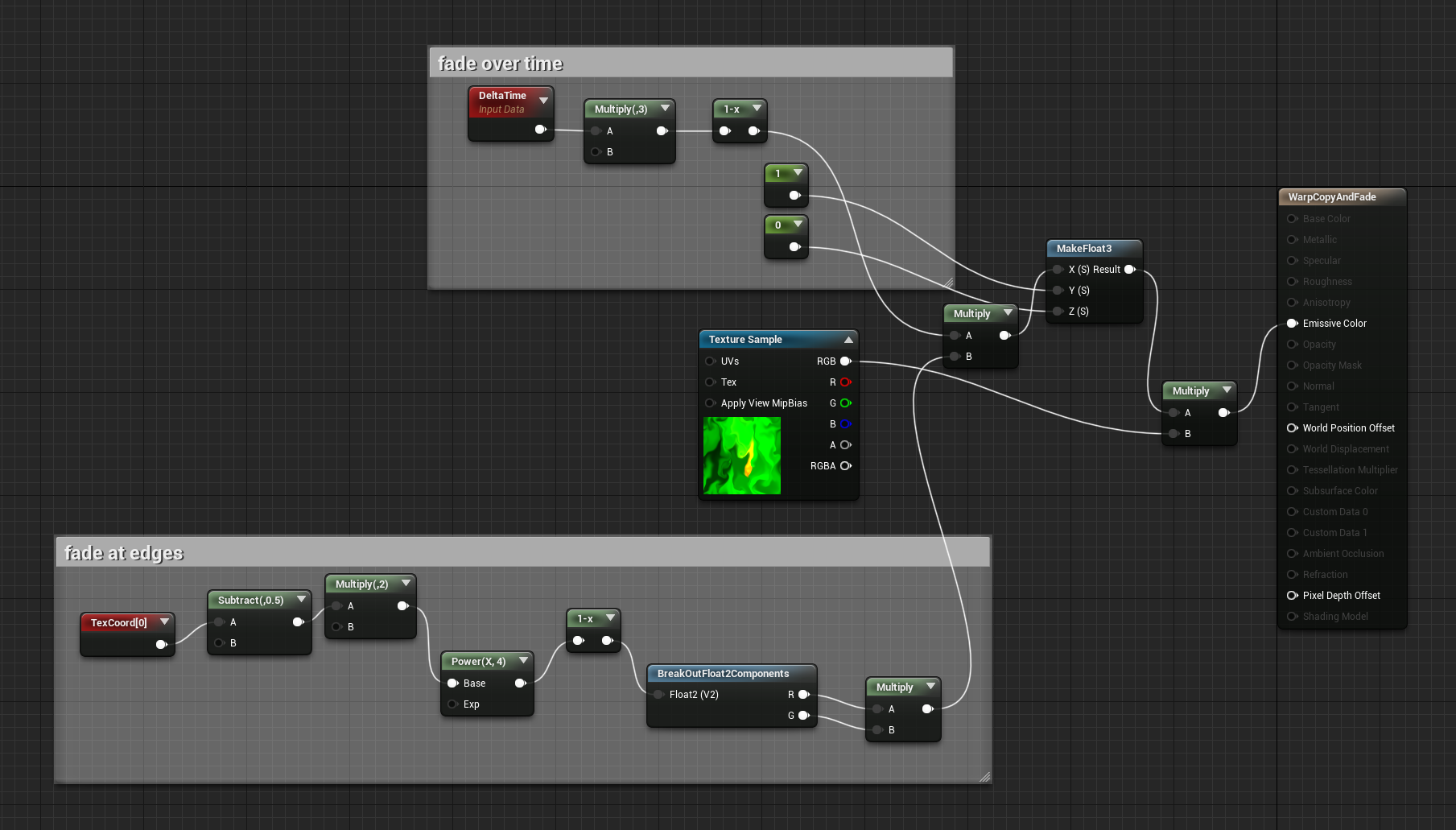
Copy / fade (blend mode Normal)
Takes the previous frame contents (from the scratch render target) and applies a fade over time (the upper section) and at the screen edges (the lower section). Note that the fade is only applied to the red channel (density) so that it doesn’t mess with the green one (color mix).
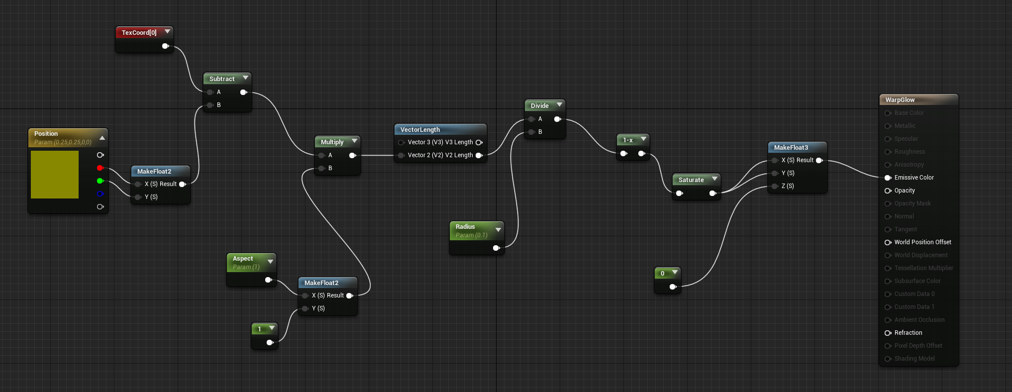
Glow (blend mode Additive)
Takes the parameters set by the blueprint for position / aspect / radius and draws a circular glow to both the red and green channels, added to what’s already there because of the additive blend mode.
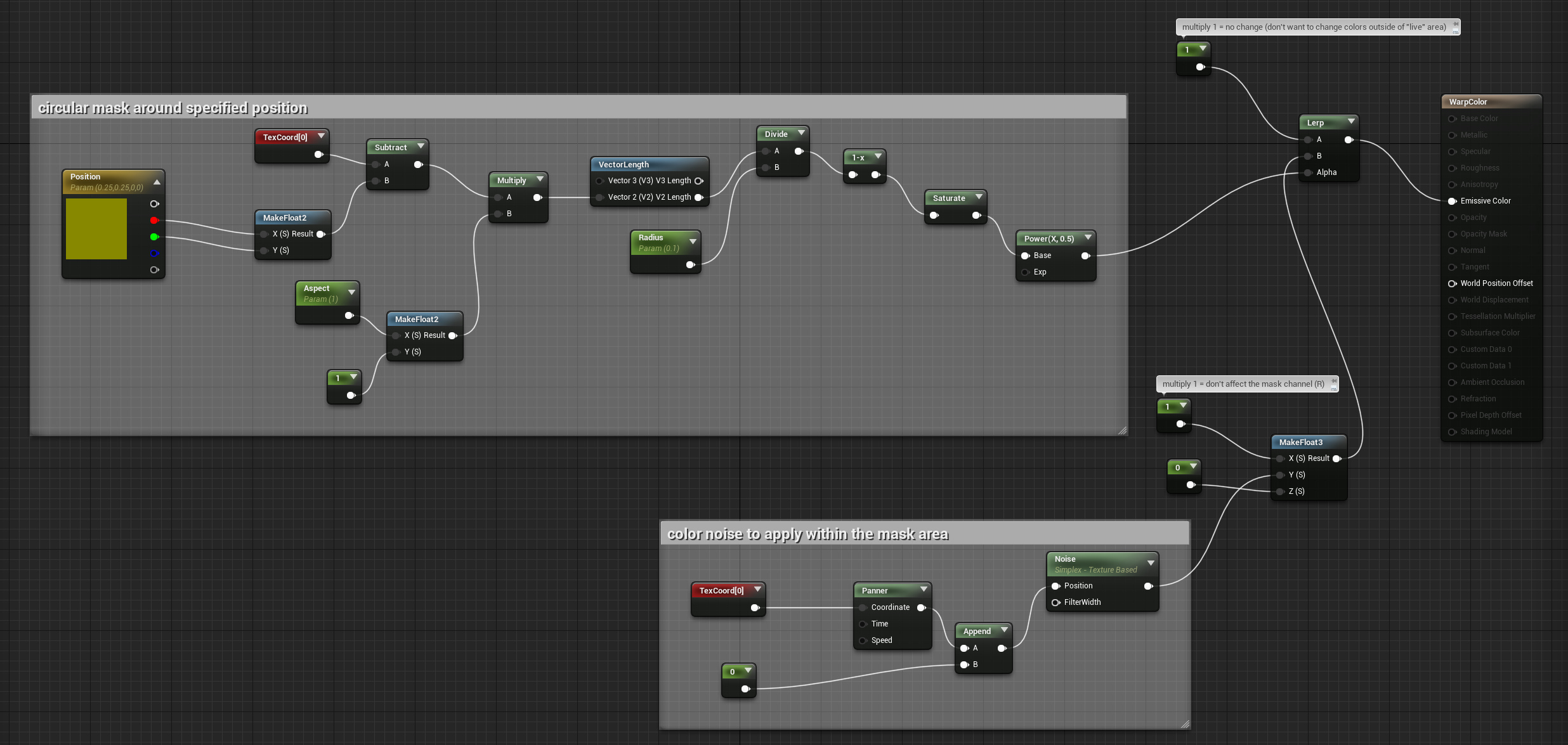
Color (blend mode Modulate)
Using the same logic as the glow material for the mask, multiplies the green channel (the color mix value) with some noise, leaving the red channel untouched.
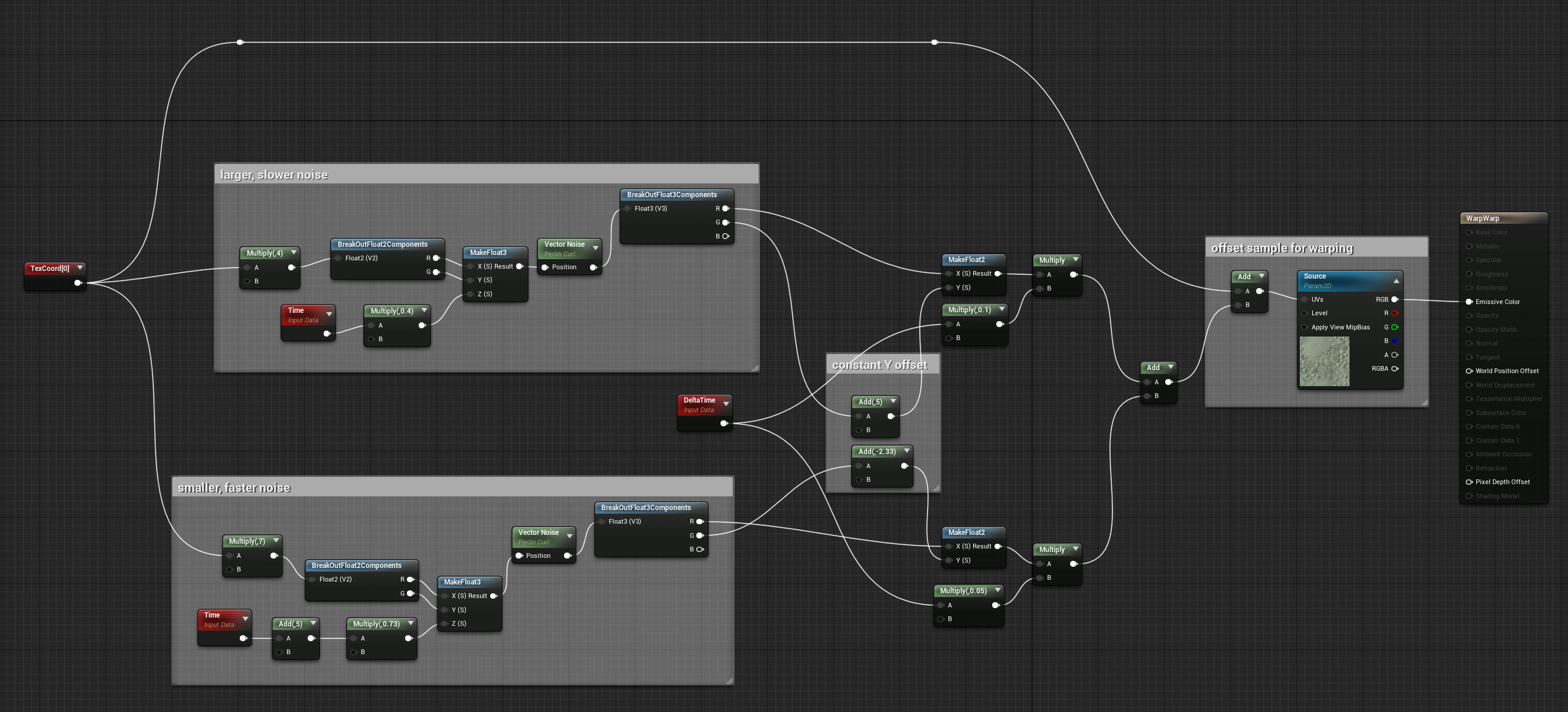
Warp (blend mode Normal)
Samples the supplied texture (the scratch render target) with a slight noise offset, effectively warping it a little bit along that noise every frame.
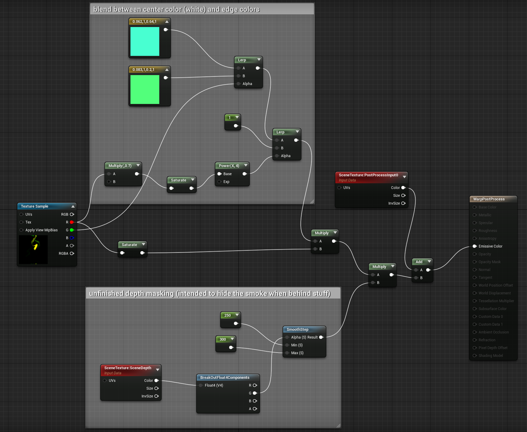
Post-process
Turns the red/green mask texture into the final colors that’ll be blended into the camera view. The green channel is used to blend between the actual colors and the red channel is used to mask the result with where the smoke is, as well as to add a white “core” to the smoke.
That’s pretty much it! I hope this explains things well enough; if you’ve got any more questions about it, please let me know.