I am currently trying to solve a certain technical art challenge I am facing. Not sure, if this is the correct place to ask since most of the posts seem very artsy and less tech art related. Are there other forums/discords you could recommend for people wanting to learn the tech art side of things regarding VFX?
Now, to my main question:
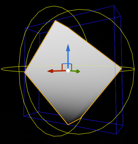
My goal is to create a shader (and script, if necessary) to fill any mesh with a gradient. The challenging part of it is that I want the gradient to always be level to the ground. In other words, the gradient should always be top to bottom while my mesh may rotate.
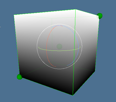
The first thing I tried was using world space or various approaches to triplanar projection, but I always end up with the same problem: I want the gradient to “scale” with the mesh. So, imagine having a gradient going from full white (1 - top) to full black (0 - bottom). Now, I want this gradient to fill my mesh from top to bottom. However, when I rotate my mesh, I want the gradient to adjust itself to the “new height” of the mesh so that it still goes from full white at the “new top vertex” to full black to the “new bottom vertex”.
Ideally my gradient would also scale up, if I scale up my mesh inside Unity, but it’s not a high priority. My main concern is that I want to be able to give a mesh a gradient that’s always level to the ground.
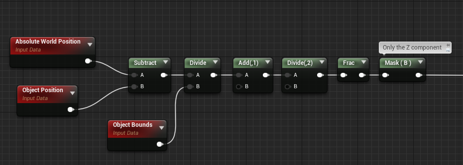
Many of the things people post here are technically challenging, not just “artsy”. What you need is to get the absolute world position, transform it to local space and divide it to the local bound size of the object (get the minimum and maximum height of the object in local space), then just mask the height axis and you would have a height gradient. That is the way we do it in Unreal.
I am not that familiar with unity but you can solve this by just using basic linear algebra. you could just use the local space location and the rotation matrix of your mesh to just perform object to world transformation without the visual scale. then use the resulting height value to make the gradient. if you don’t have access to the unscaled transform you could make this a material parameter.
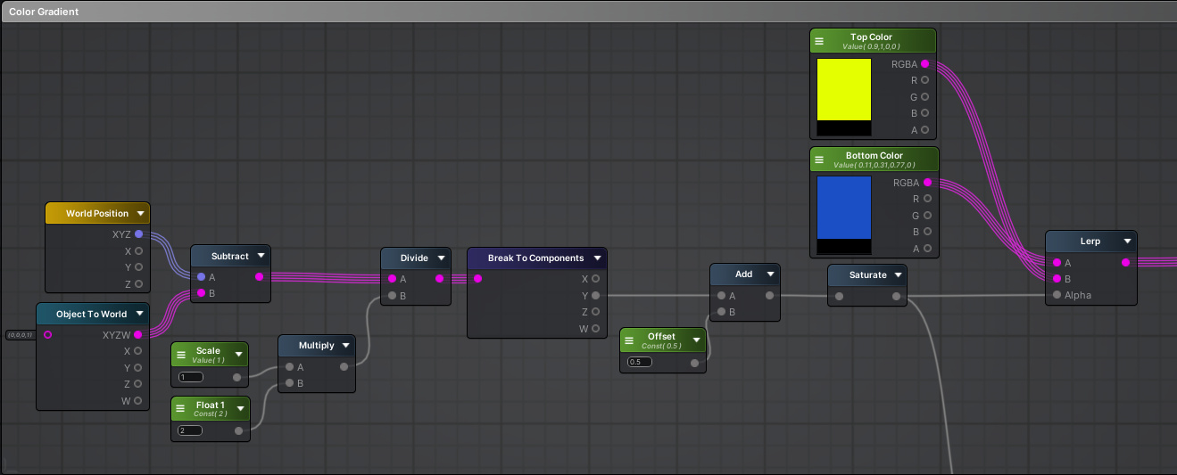
Thanks a lot for all the answers, I really appreciate you sharing your knowledge! I’ve also asked this question in a Discord and someone helped me and basically came up with this solution in Amplify. It works perfectly, but I don’t feel comfortable with the math behind it and would like to demystify every step to fully understand what’s happening. I think that fully understanding the math behind what’s happening here could be super beneficial for me with future shaders/vfx.
Maybe someone could explain this like I’m 5 years old. I will try my best to start to give you an idea about how much of it is clear to me right now:
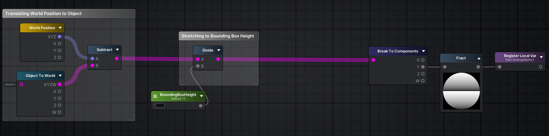
First, the object’s position in the world is subtracted from the world position in order to “move” the gradient to the right spot and also make it move with the object to make it look like the gradient is “inside” the mesh.
Question: While I understand the basic principle behind it, I’m a little confused about the spaces and the math behind it. What exactly does the “World Position” node contain? Is it the position of each vertex in the world space and the “Object to World” Node is a single position so that each vertex is moved by the same amount?
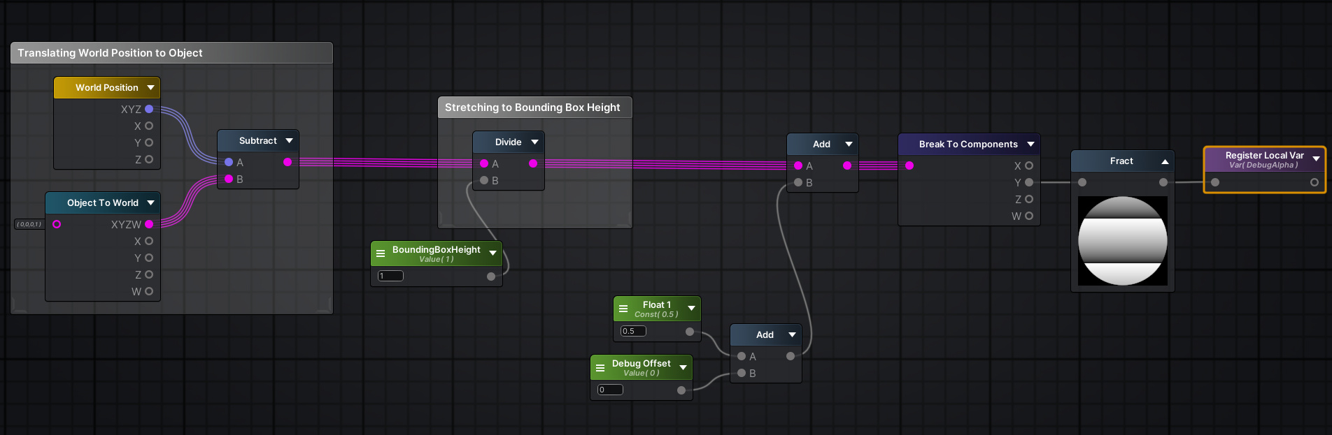
Then the values for each vertex’ “new position” is divided by the bounding box. I don’t know what’s happening here in layman’s terms. Side info: In the ASE version the “Scale” variable is fed via script and the bounding box is calculated via a collider and a script. I guess Unreal does all that in the “Object Bounds” node.
Question: I guess this is the part where the gradient is “stretched” to the size of the bounding box? Can someone give a simple example how that stretching works? I have trouble visualizing this step. At this point we only have the translated position for the gradient, but what exactly is getting divided now and what for?
In the ASE version, I now only move on with the Y-Coordinate since I want a top-down gradient and don’t need the rest of the coordinates. Now, there’s an offset added to move the gradient up by half. And in Bruno’s version you add 1 to the Y and then divide by 2 afterwards, which is basically the same thing?
Question: If it’s just to offset the gradient, why did you not move it up by 0.5? Judging from the way you came to your result, there’s probably a logical step, which could help me understand things a bit better, which in the ASE version was just cut down to save a node.
In the ASE version the result is now saturated to keep it between 0 and 1 to be used for the Lerp node and add the actual color gradient. And in your version you use a Frac node to basically do the same, I guess? I’ve read about the Frac node in the documentation and from what I understand, it’s basically like a saw graph going from x to y linearly and then instantly back to x once reaching y.
Question: Why do I need to saturate the result in the ASE version? Why wouldn’t be the values be between 0 and 1? Didn’t we stretch and offset the gradient perfectly already? And for Bruno’s UE version: why are you using the Frac node?
In the ASE version the gradient is now colored and in Bruno’s version we now mask the result to only use the Z-Coordinate, which is equal to the earlier step in ASE where we broke the component down to the Y-Coordinate for Unity.
Would be cool, if someone could shine some light on my questions and please correct me, if my understandings are incorrect somewhere.
1 - The WorldPosition node returns the absolute world position of each vertex (or pixel, if it runs in the pixel shader). So that means the position is centered around world 0,0,0. By subtracting the object position, you’re basically re-centering those coordinates around the object’s position instead of world 0,0,0.
In your example, you’re transforming 0,0,0 from object to world space, so it basically returns the object’s position in the world. It’ll return the same value for all vertices/pixels.
2 - In Unreal, the ObjectBounds node returns the xyz size of the bounding box. Dividing your position above by that will bring your values to -1, 1 range, relative to the size of the box.
3 - Since the result above is in the -1, 1 range, we need this extra step to remap that to 0, 1.
4 - The saturate node just clamps all the values to the 0, 1 range. It’s good practice to saturate things for safety, it has no perfomance cost. If you plug a value outside of the 0, 1 range to a Lerp node, it’ll extrapolate the values and can give you really weird results. Frac does what you describe, but between 0 and 1, looping back to 0 once it reaches 1 (Fmod wraps around an arbitrary value instead of 1, for future reference). I plugged a Frac just to visualize things, since it makes it more visually evident if your values shoot past the range.
5 - If you plug the result from mine into a Lerp you’ll get the same results!
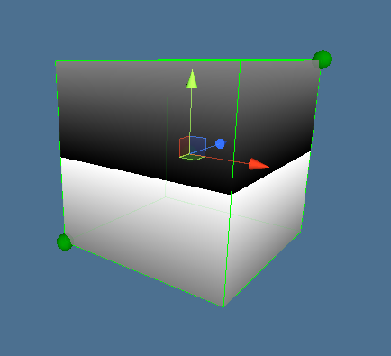
I’ve tried working with this, but there’s a bug and I just can’t seem to find the cause for this. My shader works for quads, boxes, sphere and capsules, but it will start go get buggy if the shape is a bit more irregular.
Maybe the problem is related with the difference between the bounding box center and the object center, in more complex shapes.
To make a gradient based on the (height) of the bounding box you have to tell the shader, not only the scale, but the position of the center of the bounding box, or better, the bottom-y position of the box and the height of the box.
Then, rewrite all positions based on this bottom-y position. Something like,
y_normalize = (y_pos - y_bottom_box)/y_height_box
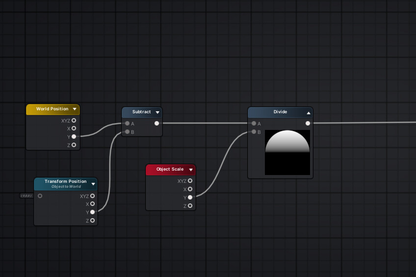
or, in your Amplify Shader replace the Object To World node with a variable with the y_bottom_box info (you are only interested in the y-component of all things)
I think, this “y_normalize” is exactly the gradient you are looking for.