
Hey Everyone, I was inspired over the holidays when an interesting artist’s work popped up on my Instagram feed. It’s a very simple and stylized effect of a grid and geometry that flips to reveal a new piece of geometry.
To give credit to the original artist, you can find their work on Instagram @hyperthalamuscorp. Below you can see the sample of the work I had described.
How to create this effect: See image below.
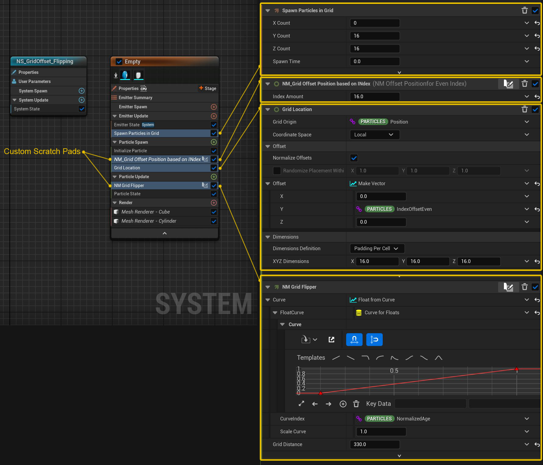
1: First I created a new empty Niagara Emitter.
2: I then added the “spawn Particle in Grid” and fixed the issues, by adding the “Grid Location” module into the “Particle Spawn”.
I decided to have a 16x16 grid, but you could add whatever size scale you’d want to have. Because this is a 2D effect, I only added to the X & Y particle count. Also, in the “Grid Location”, make sure you have “padding per cell” set.
3: While you could start to work on the flipping part, I noticed in the ref video that the grid was not in alignment, but had alternation offsets on each row, so this was the next thing I tackled.
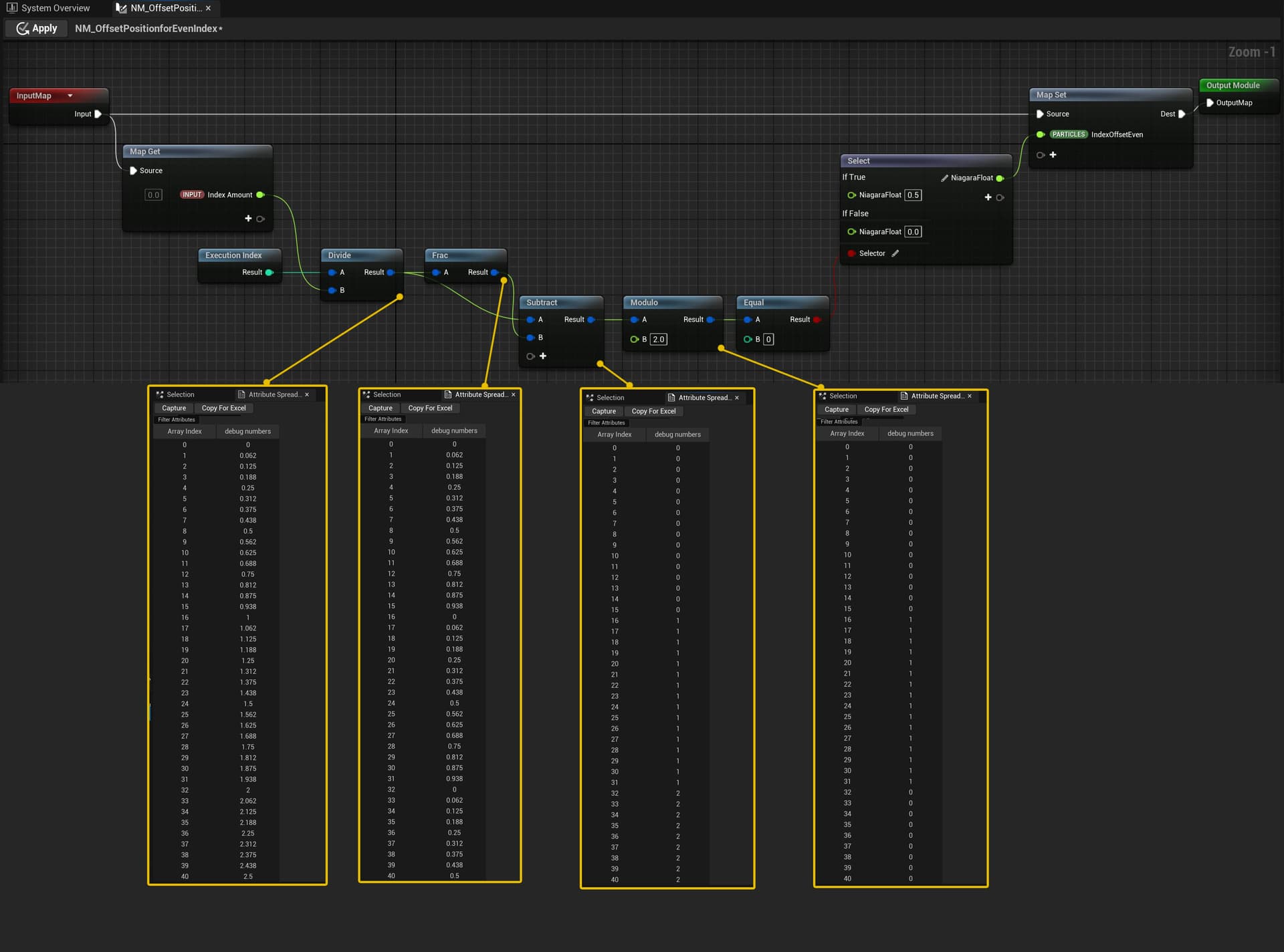
First, make sure “Enable Persistent ID” is on, as you’ll be needing each particle to have its own unique Index Value.
To get the grid particle to become offset I had to create a new scratch pad called “NM_Grid Offset Position Based on Index”. Inside the module, we’ll be entering in a custom “float” input that should reflect your grid sampling size, in my case a value of 16.
I’ve added some captured values to show you what is happening with the math operations for getting the rows to offset. They are shown in the image below. After all the math is done, I feed the values into a boolean that then goes into a switch. If the value is 1, then assign a value of 0.5. If the value is 0, then assign a value of 0. This values then get passed into a new “particle parameter” called “IndexOffsetEven” to be used later in the “grid location” offset.
4: Now that we’ve set values to have an offset on the rows of our grid we need to hook them up. Simply navigate to the “grid location” module and scroll down to find a section called, “Offset”. Here you want to break the float 3 into single vectors, or “make vector”. Now you’ll want to add the “IndexOffsetEven” parameter we just created and you should see that your rows are now staggered.
5: This module is doing all of the heavy lifting. It’s lerping between two vector positions to tell what direction should our front-facing mesh particles be pointed towards, setting that lerp value to start in the center of the particle system and lastly setting the render visibility tags once the particles have turned half way.
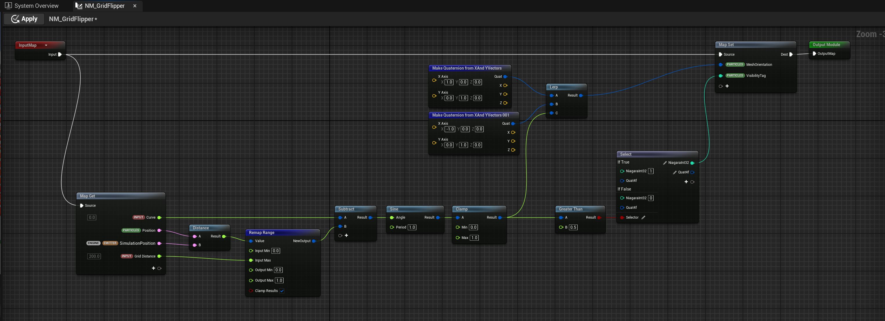
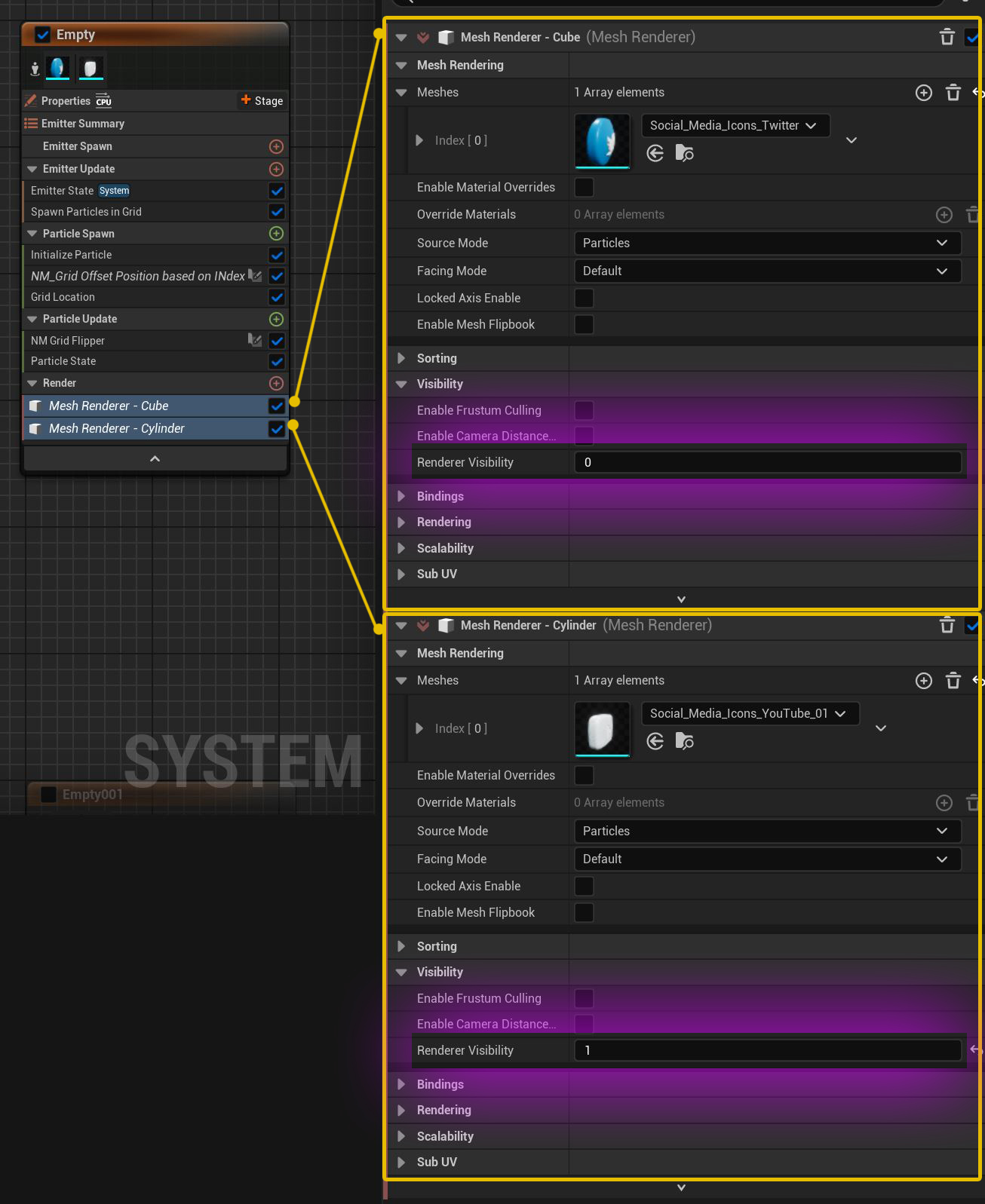
6: Setting up the Visibility Render flags is the last thing we’ll do. Inside of the “NM_GridFlipper” we took the preexisting particle parameter “VisibilityTag” and passed in either a value of 0 or 1. These values are referenced in the render setting of your particles.
In the example image below, you can see that I’m using “Mesh Renderer” and have the each mesh render sample set to use a separate “render visibility” value.
I probally glossed over a few areas, and I might come back and give more detail if people would like them, but otherwise I just had fun sharing this effect with y’all and hope you learned something new.