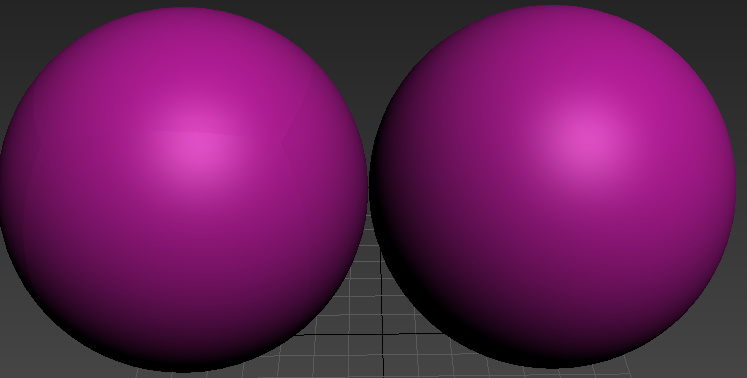
The first example of the generic long/lat sphere has issues at the poles due to the points there inherently having mismatched UVs.
Here’s the default UVs created by 3ds Max on a sphere.
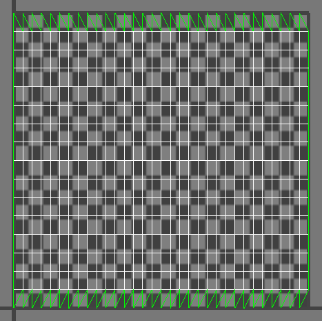
As you can see across the top and bottom, the UVs are in a saw tooth pattern. Each of those points are thus sampling a different point in the texture, thus will be offset by a different amount. One option is to weld the UVs across the top, like this:
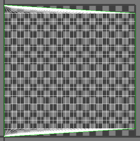
The result is now all of the vertices at the top are sampling the same place in the UVs, and now they don’t separate. It also means your texture kind of “swirls” a bit at that point.
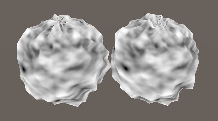
Another option would be to store two UVs, one with the poles “pinched” like this for the vertex offset, and another for the actual texture display. This could also plausible be done in the shader by checking to see if the per vertex UVs where outside some range (ie: uv.y > 0.99 || uv.y < 0.01) and use a constant value in the shader for the uv.x. I’ve also done stuff like lowered the mip level, or faded between two textures, or just faded out the displacement scale at the poles.
Now your cube-sphere is more interesting. The separation there is likely due to your normals not being correct. If you took a tessellated cube and spherified it without re-smoothing the normals I would expect to see what you’re seeing. You should be able to fix that by just selecting all of the polygons and using a single smoothing group.
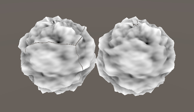
If you look carefully, you should be able to see the seams in the normals in your modelling application.