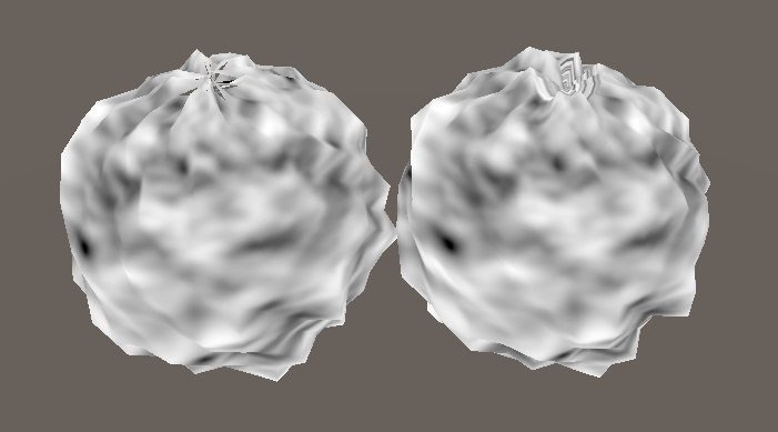
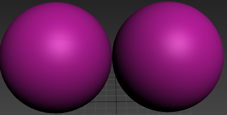
hey guys! i’d like to deform this sphere with some vertex offset according to the moving uvs in unity3d
but no matter what geometry i have used. there still has the broken surface.
how can i deal with the broken ?
3 Likes
I’m not exactly sure what you mean with broken.
Are you talking about the faces detaching from eachother or the jagged surface?
To fix faces detaching from eachother try this:
-In moddeling software, select the whole sphere and smooth completely (this makes it so that vertex indices aren’t duplicated
-Remove any uv seem possible. (this is ridiculously difficult on a sphere, but try and have the least seems as possible
-remove extrimities near the seams. The biggest reason why your mesh is tearing is because near seems your vertex offset will be sampling in completely different places in your textures, causeing it to offset with different values. if you can limit that difference, your tears will be harder to spot.
Another thing you could try is to not sample using uvs, but on world positions for example, that way you won’t have any tearing, but that has other limitations.
Hope that helps!
2 Likes
thanks a lot. i am using world position to deform it now. no tearing much better YEAH !
Make sure to use median in photoshop to smooth that cloudy noise map for the vertex offset. If the texture has too much small detail it can really screw with your world position offset. Especially if you are multiplying your texture a bunch. It can cause a pretty weird jagged effect. Cool looking ball you got there though!
3 Likes
ye. thats right. so i am using world space currently. the disadvantages is vertex offset can not deform it according to texture uvs. but i think its ok . thanks !
1 Like
I’m not sure if Unity has this, but in tearing with some meshes in UE4, you need to set the mesh to use “Full precision UVs”.
3 Likes
There’s no equivalent, because UVs in Unity are always full precision by default. You have to enable compression manually per mesh.
Well that sounds handy
The first example of the generic long/lat sphere has issues at the poles due to the points there inherently having mismatched UVs.
Here’s the default UVs created by 3ds Max on a sphere.
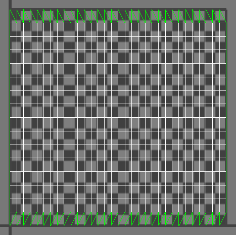
As you can see across the top and bottom, the UVs are in a saw tooth pattern. Each of those points are thus sampling a different point in the texture, thus will be offset by a different amount. One option is to weld the UVs across the top, like this:
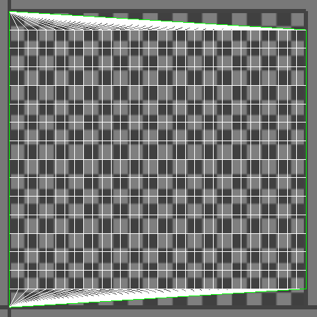
The result is now all of the vertices at the top are sampling the same place in the UVs, and now they don’t separate. It also means your texture kind of “swirls” a bit at that point.
Another option would be to store two UVs, one with the poles “pinched” like this for the vertex offset, and another for the actual texture display. This could also plausible be done in the shader by checking to see if the per vertex UVs where outside some range (ie: uv.y > 0.99 || uv.y < 0.01) and use a constant value in the shader for the uv.x. I’ve also done stuff like lowered the mip level, or faded between two textures, or just faded out the displacement scale at the poles.
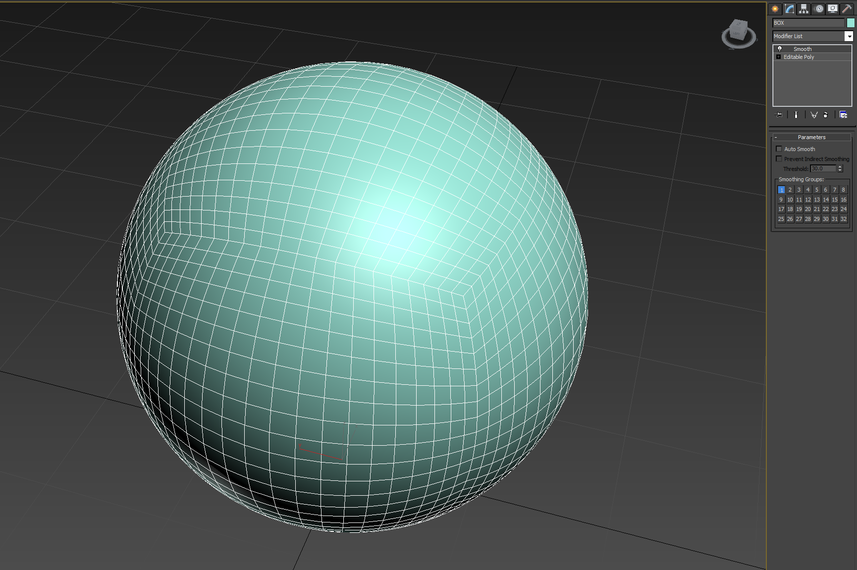
Now your cube-sphere is more interesting. The separation there is likely due to your normals not being correct. If you took a tessellated cube and spherified it without re-smoothing the normals I would expect to see what you’re seeing. You should be able to fix that by just selecting all of the polygons and using a single smoothing group.
If you look carefully, you should be able to see the seams in the normals in your modelling application.
2 Likes
wow, i think two uvs must be the best way to fix this issue!
and i have faded out the displacement scale at the poles by vertex color as well.
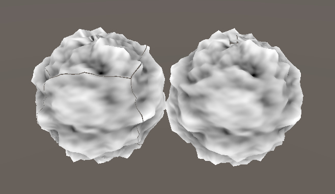
as for cube-sphere.it still have some problems.
i used a smooth modifier apply to the object. but it still tearing.
did I use the wrong modifier or I need houdini to create a cube-sphere?
2 Likes
大佬可以去cgjoy去发一篇技术帖吗????
1 Like
Looks like the lower half of the mesh were flipped ( or mirrored)in the UV unwrapping process.
2 Likes
Yeah, like @raytheonly already mentioned, it’s because of the UVs. In the first post it looks like you applied some kind of spherical UV mapping to the cube-sphere, where as here you’re using the default box’s UV. That means you’re going to get the same kind of seams in the UVs, which will result in seams in the displacement.
So there’s one other option that I didn’t bring up. And is what I actually do today. The problem with any of the options above is you’re trying to map a repeating 2D texture onto a 3D surface with no seams. This is a difficult problem to solve nicely. So instead you could use a 3D texture or noise function and use the mesh’s vertex positions rather than the UVs to sample from.
1 Like