Hi!
I have wrote an article with detailed explanation of my Point Clouds Morphing FX for Unreal Engine 4.
Hope you like it, sorry for my not ideal english knowledge )
What is the Point Clouds Morphing?
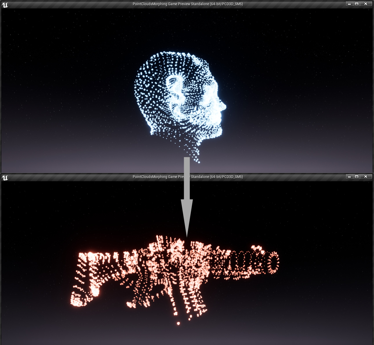
It’s smooth transformation FX between two 3d models represented as particles in a 3 dimensional space. I have made PCM effect about two years ago:
Before starting work on VFX i have define technical requirements for final VFX version:
- Only using Unreal Engine 4 BluePrints without any C++ code
- No have and massive calculations on CPU
- Particle count limit must able to rendering mid detailed 3d model
- Correct morphing any start particle count to any destination countлах лимита
- Custom color, scale, emissive light, etc parameters
- Must be able to be extensible with C++ for increasing particle counts
So, we have two 3d models and we want to deal with transformation from first model to second.
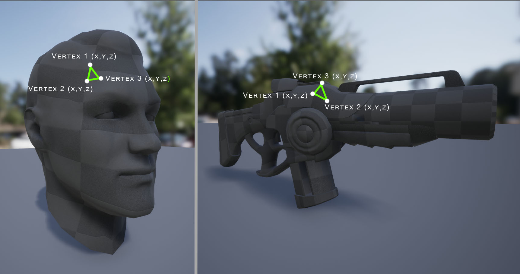
As we know, 3d model contains information about vertices. Based on the vertex information, GPU knows how and where to draw triangles.
But we need only vertex world coordinates that describe X, Y and Z float values:
Obviously that providing calculation for the vertices on CPU is not really an effective way, so we will do a job on GPU.
After some research and brainstorming time - the easy and clear way to store data and pass to GPU render - bake vertices coordinates in to the texture. As result we have Point Cloud texture with packed data in a special manner.
Baking Point Cloud texture
Next question is: how to bake vertices coordinates in to the texture only using UE4 BluePrints?
I have used RenderTarget and drawing directly into canvas. In fact we draw in an texture:
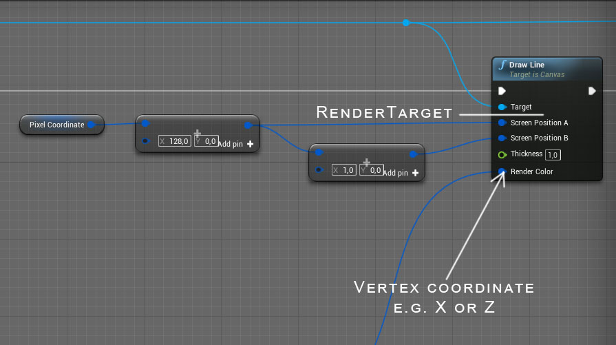
We get all vertices from a 3d model (that is possible only with Enable CPU access flag in UE4) and pack values into the texture. As result:
More detailed info about Point Cloud texture data format:
As we know vertices are stored in float format. One float is equal to 4 bytes or 32 bits.
Accordingly for storing info about 3 components (XYZ) for one vertex we need 12 bytes.
That’s too much and will require bigger texture size for storing data.
By this reason i have limited maximum size of 3d model that can be used for VFX in range: -32767 to +32767
And now for storing one vertex data (X, Y or Z coordinate) we need only 16 bits of 2 bytes or bytes per one vertex.
16 bit is used as a sign + or -, other 15 bits are used for setup a natural value
For packing all three components of vertex coordinate need 6 bytes instead 12.
Of course is possible to pack real float value in to the data, but VFX is locally used and unlikely
need to store real and precision float values.
Also must keep in mind about GPU depacker complexity and shader instruction count for decoding Cloud Texture for assembling in to the value.
16 bit value consists of two bytes - Hi Byte and Low Byte of rounded integer value.
For example if coordinate value = 345,783 then algorithm round value to 346
We don’t not need a fractional part because it is not polygons, just setting up for a particle center coordinates closer to original vertices coordinates form 3d model.
For example, 12345 value will be represented as two bytes:
HiByte = 48
LowByte = 57
48 * 256 + 57 = 12345
Then our two bytes converted into linear color for the pixel.
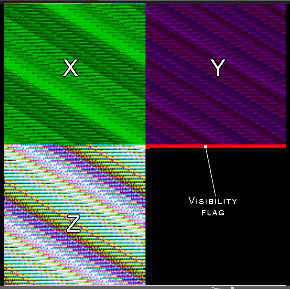
Third component of linear color is used as a visibility flag:

In the video above we draw pixel color to RenderTarget texture:
X, Y and Z components are drawing to texture RGB channels with special offsets:
X with offset 0 by horizontal and 0 by vertical
Y with offset 128 by horizontal and 0 by vertical
Z with offset 0 by horizontal and 128 by vertical
Visibility flag offset 128 by horizontal and 128 by vertical
The RGB packing data format is:
RG - X component
BR - Y component
GB - Z component
Point Clouds Morphing always provides a rendering defined count of particles. But different models contain different vertices count. If the amount of model vertices is less than defined particles count then i have marks nonexistent particles as invisible.
Marked red - it’s visible particles (vertices) that exist in the source 3d model.
But coordinate components (XYZ) is duplicating to a maximum possible limit 16384.
Rendering on GPU
I have been using Unreal Engine 4 Instanced Static Mesh Component feature for rendering particle geometry. Instanced Static Mesh feature it’s great way to render massive amounts of the static meshes without significant loads of CPU and GPU.
All geometric and pixel calculations happen inside of material. Material has parameters:
- Source cloud texture
- Destination cloud texture
- Morph stage (0…1)
- Particle color and emissive power
- Particle size and scale
- Additional distortion
- Rotation and location values
As result: the material includes 216 instructions and using 5 texture samplers:

What we do inside:
- Decoding HiByte and LowByte from Cloud Texture and encoding to coordinate for particle center.
- Calculate rotation ant transform for of decoded particle center point.
- If the particle is not visible (visibility flag = 0) then draw particle with 0,0,0 scaling.
- If destination Point Cloud has bigger particle amount than source then interpolation scale value from 0 to 1.0
- If destination Point Cloud has lower particle amount than source then interpolation scale value from 1.0 to 0
- Linear interpolating between source and target particle coordinates, color, scale, etc…
Because particle coordinates are duplicated, we have visual effect that particles are spawned at the existing locations.
And in other cases if target Cloud has a lower amount of particles then we have visual fidelity that particles fly to exist point.
You can add custom distortion for additional local particle movement and custom scale value.
Some hack I have made for detecting particle index in the Point Cloud texture.
Unfortunately it is not possible to get an Instanced Mesh Component index inside of material. PCM is spawn each Instanced Mesh Components with some offset. For example 0,1,2,3,4,5,6……16384
Offset difference (World Position of component) is used as Cloud texture index. The particle is a simple quad mesh of two triangles and always facing the camera view.
Result of geometric calculation is connected to the WPO input of UE4 material domain.
Conclusion:
100% on the UE4 BluePrint
PCM is fully GPU calculated except for some light logic like Cloud texture switching, setup material parameters like particle color, morphing stage, custom scale, etc…
16384 particles limit (can be extended with C++ version).
Point Cloud texture is 256x256 RGB, not require much space.
2 draw calls rendering.
Is possible to bake any 3d model limited 16384 vertices counts and size -32767 to +32767.
FX has been tested on the PC (SM5), PS4 and Nintendo Switch.
Final result:
https://youtu.be/KmdSFClL5-Q
Thanks for reading!