This is some really nice stuff! Thanks for showing it MrBrouchet
1 Like
Hi,
Having trouble making the screen space transform part. Could you show or give a more detailed explanation on how to change the standard way where the lines move with the camera?
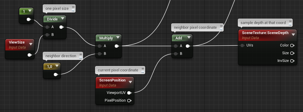
basically the postprocess material is based on this core part:
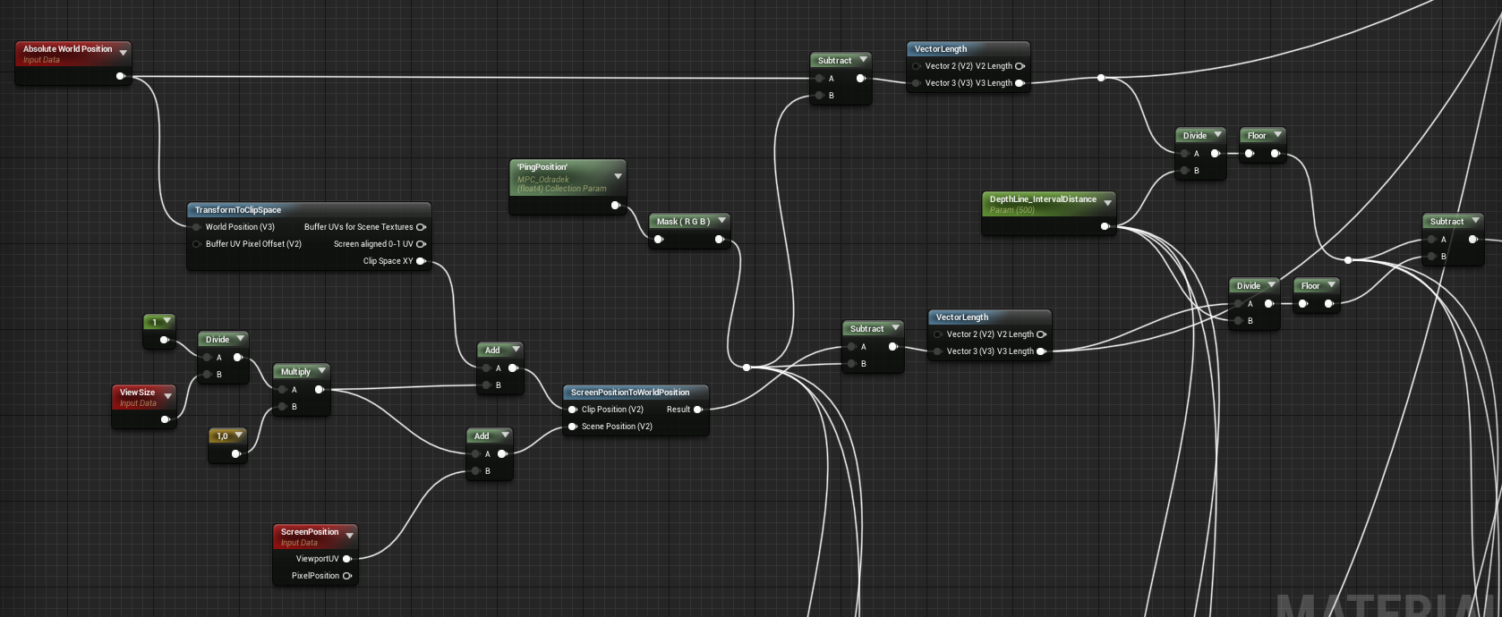
It’s just repeated 4 times for the horizontal and vertical directions (this is the computing for the left pixel, as you can see on the ConstantFloat2 node that is [1,0] ). Then everything is added-up and saturated.
The ScreenPositionToWorldPosition function is the custom one I created, mentioned above.
PingPosition is the float3 location of the actor that activates the scan, set in BP through a MaterialParameterCollection.
Hope this helps
2 Likes
Awesome, thank you! ![]()
1 Like
Hello! I am trying to recreate Death Stranding’s environment scanner as well and have been following your tutorial to accomplish this. I was wondering what the Odradek Scanner PPVolume was. I assume, by the name, that it is the Post Processing Volume but is it attached to the Third Person BP or are you accessing it from the Scene somehow?
For the record, this is not really a tutorial ![]() At the very least it’s a recorded adventure, with a part of me trying to explain things that might be too technical
At the very least it’s a recorded adventure, with a part of me trying to explain things that might be too technical ![]()
To answer your question, yes I’ve being using a PostProcessVolume actor that is present inside the character BP. This was the simplest approach I had on my mind to implement the effect, but I’m not sure that it’s the best one ![]() I guess your could probably apply the postprocess directly on the character’s Camera if your don’t want to use a volume.
I guess your could probably apply the postprocess directly on the character’s Camera if your don’t want to use a volume.
Gotcha. Well, it seems like it was a fun adventure!
Thanks! Gotcha. I really appreciate your reply.
1 Like
Hello again! I tried following the MVP Matrix link for this section of your work but it says that the page no longer exists. Would you mind taking a look to make sure that the link works for you?
Also in the part where you are converting the Sobel Matrix to apply to the WorldSpace information, what do you mean by “…just take the inverse view size (1/ViewSize), multiply it by your 2D Direction, and add that to your screen cord.”
From the the sounds of it, I need to modify the internals happening with calling the various pixels.
Do I bring the Absolute World Position and TransformToClipSpace into the Sobel or do I attach it together after I have got the sobel matrix working?
1 Like
This is very amazing!!! Great job!!!
1 Like
The link I gave to a explanation of the MVP matrix is still working for me. But, you can also find a lot of information elsewhere about matrix transformation and perspective for 3D rendering.
Matrices are the basic mathematical tool we use to transform (eg. move, rotate and scale) objects in a 3D engine. You can begin to understand how it works with these few videos here, here and here.
What we call the MVP is the Model-View-Projection matrix, which transforms any object in your scene into a perspective-correct shape on your screen in order to draw it/rasterize it (through an operation called the ‘perspective divide’). Because when you think of it, any 3D object must be ‘projected’ on a 2D plane which is your screen, before you can ‘see’ it.
When the perspective divide happens, the distance from the view position to the vertex position of your object is stored and can be interpreted as ‘depth’. Edit: Actually, it seems that you already get this depth information when applying the Projection matrix, before the Perspective Divide. View-space Z value gets stored in the 4th component of your position vector, which becomes your clipspace depth (and I suppose this is the value that gets compared and written to/against the depth buffer).
This 4th component will then be used for pespective division when you want to project your object onto your normalized viewport coordinates, scaling your perspective frustum into the perfect box that is your screen.
Or, at least that’s what seems to happen in OpenGL. Maybe someone related to graphics rendering can step in to add details, or correct me if I’m wrong!
About the “sobel” operation, no need to modify any internal rendering or anything. What I meant is that, for the operation to work, you need to ‘sample’ information on neighboring pixels.
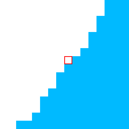
Let’s say I want to detect if this pixel in red is an edge of something, and the blue pixels in the image are belonging to a triangle that is close to the camera while the white pixels are the skybox background:
What I do is sample every neighboring pixel value like this:
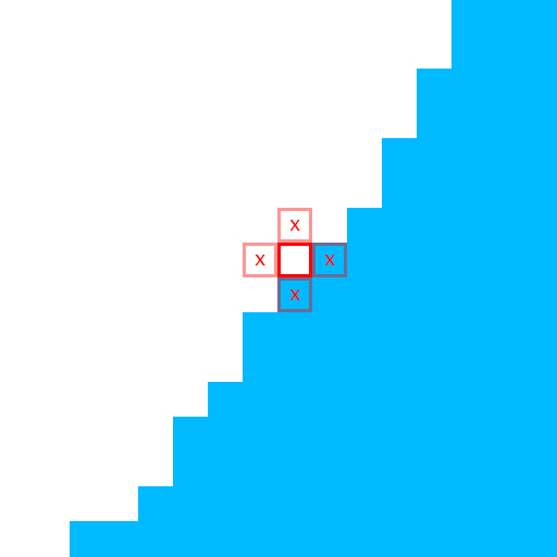
If the sampled value is, for example, the depth of the pixel, then I can compare any pixel’s depth with the depth of it’s neighbors. This is done by doing something like,
result = (currentPixelDepth - leftPixelDepth) + (currentPixelDepth - rightPixelDepth) + (currentPixelDepth - topPixelDepth) + (currentPixelDepth - bottomPixelDepth)
The result will be the final addition of the depth difference for every neighbor pixel. The greater the depth differs, the greater is the result. So you get a result that outputs “depth difference”. So it’s basically outputting an edge detection. In my case, the depth difference between the blue triangle and the white background will be very large, so I will get a white output at this pixel’s coordinate (don’t forget to clamp/saturate!).
So how do you sample a neighbor pixel huh?
Easy, let’s say you can get any current pixel being processed by your shader with this simple node:
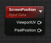
Then, if you just add any number in U or V, you’ll be able to get the coordinate of another pixel during the current process of your shader, right?
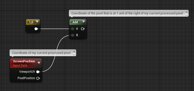
So how do you get the pixel that is you exact neighbor? 1 unit on the right here we’ll be the pixel that is 1cm across since UE4 works in centimeters. We don’t want that. We want the pixel that is 1pixel across.
A good way to do that is to calculate the size of a pixel in centimeters!
This is possible with this node:
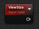
It outputs a 2D vector containing the current size of your viewport in pixels. So if you are in fullscreen 1080p, it will output a vector like this: float2(1920, 1080) Taking the inverse (or more specifically, the reciprocal) of that will simply give you the size of a single pixel for your current resolution:
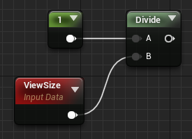
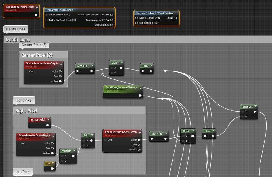
Then you just have to multply any 2D vector with this to scale that vector to a single pixel length, so the end result of my pixel neighbor sample graph looks like this:
Read again what I’ve posted on this thread, you should have answers for everything. For now you’re sampling the depth of neighboring pixels (good) but as I mentioned during my adventure, this is not sufficient to recreate the full effect that we see in the game…
Also, as @max_rudakov mentioned earlier is this thread, an authentic Sobel operation is a bit more advanced than that, as it is using what we call a ‘kernel’ in a two-pass calculation. See this video for a detailed breakdown of a real Sobel.
1 Like
Wow. Thank you so much MrBrouchet. I really appreciate the depth (pun not intended) and detail you put into this explanation. I’m really new to working on Shaders so I don’t know what a whole lot of nodes do besides the basic ones, and I know even less how to appropriately and most effectively connect everything together to get a specific result. Again, I really appreciate it. ![]()
1 Like
Hello again! I have a few questions for you again if you have some time.
-
I was wondering if you could break down your Odradek Color Module a bit more as the picture in the post doesn’t really show the specific node construction of the Blueprint very well.
-
The Module.PlayerPosition should be a Vector right? But isn’t position data a Vector 3 variable?
-
How do you get information for the Distance Field gradients? Is it by enabling Generate Mesh Distance Fields in the Project Settings? Every time I try to test out what kind of infomation the node has visually by using a basic shape with a material that is using the shapes positoin and the Distance Field Gradients node, it just comes up Black.
Sorry about the list of questions. I really appreciate the help that you have given so far. Thank you.
Sorry for the late answer, been busy with other stuff lately,
- There’s nothing fancy in this module, just a bunch of behavior for color based on simple data like Particles.Position and Particle.NormalizedAge. Here’s my input data:
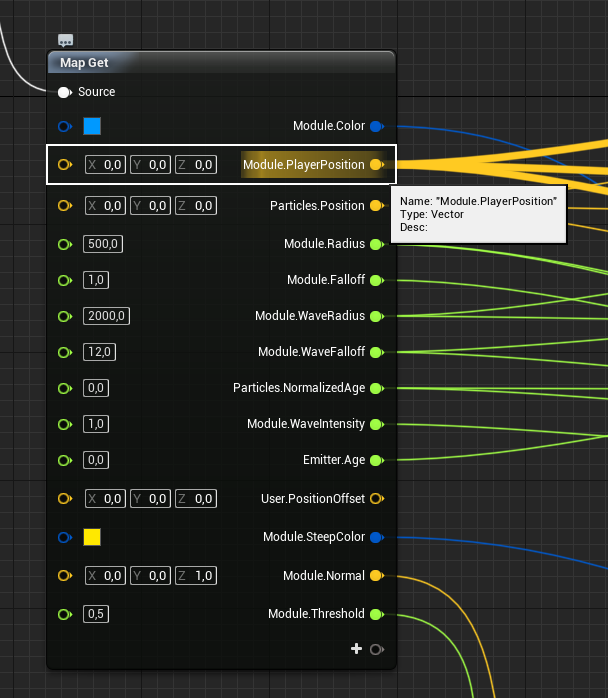
Be noticed that I used this module at Update stage, meaning these datas are updated every frame.
I’m not gonna break this down node by node, because it’s just a bunch of math everywhere actually and it’s not very clean nor optimized, and because I’m lazy. But it’s just a bit of vector math using time for animation.
There’s another view of a second Map Get in the module, this one is for making the circle wave that originates from the player when the grid is spawned:
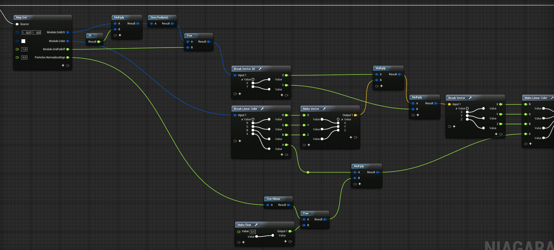
-
You can see in my first image that Module.PlayerPosition is indeed a Vector data, so I’m not sure what you mean?
-
By saying “distance field” I do not refer specifically to Mesh Distance Fields, which is a feature specific to UE4. A Distance is just a mathematical tool that is often used in 2D or 3D games, and is basically just a vector’s length. You can achieve a lot of interesting things with that tool, and it can become a distance field whenever you have a bunch of distance data scattered in space. Like for example every particle’s distance from themselves to the player’s >> you could use that to, let’s say, have the closest particles fading their alpha. And maybe you could add the particle’s ticking age in the mix, to have this alpha being animated? Or maybe any point in space could theoretically store it’s distance from the closest static mesh in the scene and you could do weird awesome stuff… I wonder how you would call that ;p
Did you end up doing any sort of low-pass filter / dx/dy network + smoothstep implementation to “anti-alias” the outline?
l’ve messed around with bits and pieces of your code and other outline shader implementations but they always fall apart when it comes to aliasing. And using TAA makes the lines look like hot garbage.
Nope, just the filter. I didn’t thought about using a smoothstep, interesting idea ![]()
I ended up disabling TAA indeed, also for performance reasons.
Hi, I have been following your path to recreate the effect. I found it really helpful and interesting. Thanks for that. For now I’m stuck by one of the steps in Niagara.
As I followed the GDC 2019 training session, the particles were in a mass eventually, even if I use the Grid Location at first. However, the particles should be perfectly organised like grid. I can’t find out the place to adjust it.
Hey Levin,
I can’t say much about your specific problem without additional infos ![]() Are your sure your Grid Location module is in the right place on your module stack? Be aware that, In Niagara, each module is read by the system from top to bottom. If you use Grid Location and then another module right after that changes your Particle.Position values, it will override your Grid Location values.
Are your sure your Grid Location module is in the right place on your module stack? Be aware that, In Niagara, each module is read by the system from top to bottom. If you use Grid Location and then another module right after that changes your Particle.Position values, it will override your Grid Location values.
Any hopes of ever getting a tutorial or perhaps a look at the project one day? I’ve been waiting since your adventure started in hopes that it will either get completed and perhaps project shared or a tutorial made or that someone cracks based on your posts and snippets and recreates it, but so far no tuts on this and I tried to follow some of the snippets but failed miserably. xD
Hello TwitchingPsycho (welcome on the RTVFX forum!).
A full tutorial, either a video or a blog post, would totally be something cool but I’m afraid it’s also A LOT of work to do and I’m kinda occupied on other things right now I’m afraid. I actually hoped this thread would be a good start for anyone wondering how to tackle this specific case, and just looking for clues. Because it’s quite an advanced-level effect that brings up a lot of different subjects (shaders, image postprocessing, scripted particles, BP, …) so doing a full tutorial would be quite a challenge, if you really want it to be instructive.
I could probably share the project files though, I’m not sure what’s the best solution for that?
1 Like
Hello MrBrouchet,
Pretty interisting, congrats! Due to the nature of not being a “tutorial” I would appreciate to be able to see the project files for further studies, if you still willing to share of course. I tried to reproduce the effects already, but as others too, I hit some walls especially in the 2nd part.
Looking forward to it and thank you in advance!