Mostly explained in the video. Was inspired to try an idea on lighting fx explosions. I like how it turned out. next step is to get the rotation of the smoke object to be as I want them by rebuilding this in Niagara.
It is nice to see some endeavors for visualizing light emission properties in particle volumes & meshes. The results are really neat! ![]()
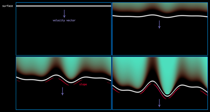
Something else that could help bolster this further (even in a stylized effect), is to approximate how much your mesh / volume surface is displacing over time. By tracking the rate of change at a given point, you could map that to a velocity range that would represent heat & expansion. This way, you wouldn’t have to try to guess a volume gradient by hand. It would also conform to the topology of your mesh surface (which is a big plus). You could then do some extra magic on top by isolating crevices and pumping the heat production up in those areas as well.
Here is a quick “visual” example to hopefully help with the description.
Imagine the white line being the surface of your geometry (let’s say a sphere). As heat is produced and the gas begins to expand, it pushes out (or in the case of the image “down”) onto the surface of the geometry “the white line”. When this happens, the surface will begin to displace based on the rate of expansion per vertex based on the volume and gas characteristics “pushing against” it.
Here is the code (paste it into a shadertoy shader) if you want to mess with it.
Please forgive the formatting… and everything else, it is late and I don’t know where I am or what I am doing ![]()
#define ASP_RATIO iResolution.x/iResolution.y
#define AMPLITUDE 0.3
#define FREQUENCY 4.0
#define OFFSET 0.0

float topologySurface(in float curve, in float p, in float width)
{
    float padding = 0.01;
    float lineObject = smoothstep(p-width, p+padding, curve)*
        			   smoothstep(p+padding+width, p, curve);
	return lineObject;
}

    void mainImage( out vec4 fragColor, in vec2 fragCoord )
    {
        vec2 uv = fragCoord.xy/iResolution.xy;
        vec2 uvRemap = vec2(((uv.x*2.0-1.0)*ASP_RATIO),
                            (uv.y*2.0-1.0));

float curve_a = uvRemap.y + (sin(uvRemap.x*FREQUENCY)*AMPLITUDE)+OFFSET;
float curve_b = uvRemap.y + (sin(uvRemap.x*FREQUENCY*1.250)*AMPLITUDE)+0.5;
float curve_c = uvRemap.y + (sin(uvRemap.x*FREQUENCY*1.80)*AMPLITUDE)-0.1;

float topology = (curve_a + curve_b + curve_c);
float fExpansionRate = smoothstep(((curve_a+curve_b+curve_c)/1.50/abs(uvRemap.y+0.4)),
                                 ((curve_a+curve_b+curve_c)*0.275), uv.y)*step(0.0,topology);

float surface = topologySurface(topology, -0.2, 0.1);
float surfaceForSlope = topologySurface(topology, -0.5, 0.1);
float s = dFdx(surfaceForSlope);
if (s<0.075){s = 0.0;}

vec3 surfaceColor = vec3(surface)*vec3(1.0, 1.0, 1.0);
vec3 fExpansionColor = mix(vec3(0.99, 0.2, 0.05),vec3(0.3, 0.872, 0.74), vec3(fExpansionRate))*fExpansionRate;
vec3 sColor = vec3(s)*vec3(5.0, 0.0, 1.0);
vec3 rFrame = surfaceColor + fExpansionColor + sColor;

fragColor = vec4(rFrame,1.0);
}Yeah I see what you’re doing. Very cool, it gives me ideas on how to improve the system, altho I’d go about it in a more unreal shader graph way. I’ll have to test some ideas before I know what will help/make a noticeable difference. Thanks for the reply, this is great.
amazing…i will try this… thnx for sharing …
thanks for your share

